
US $14000
| Condition | Used
:
An item that has been used previously. The item may have some signs of cosmetic wear, but is fully operational and functions as intended. This item may be a floor model or store return that has been used. See the seller’s listing for full details and description of any imperfections.
|
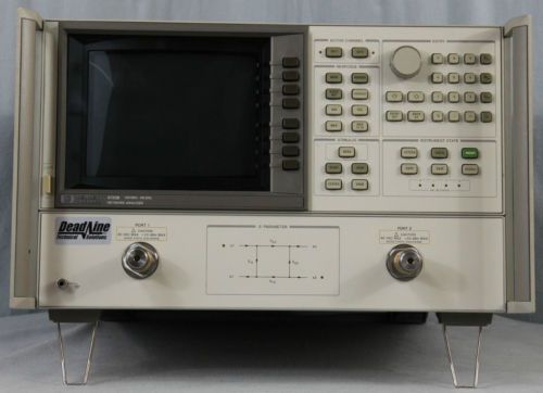
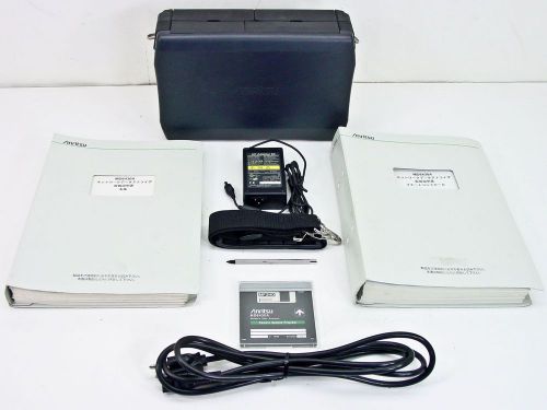
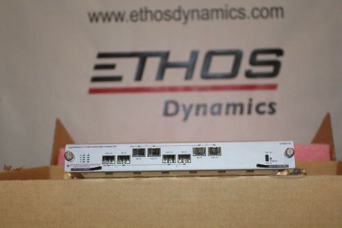
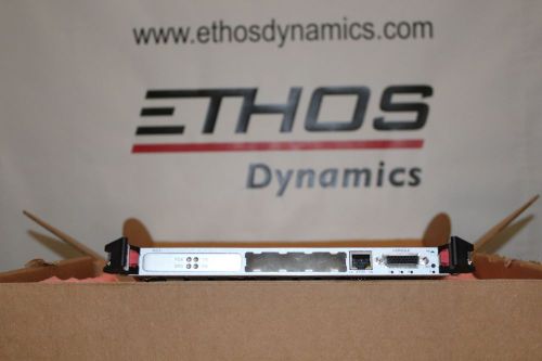
| Seller Notes | “Very minor cosmetic imperfections. Photograph is actual unit, not stock photo.” |
Directions
Similar products from Network Analysis Complete Systems & Mainframes
Agilent / HP 8753ES w/Opt:H39 S-parameter Network Analyzer, 30 kHz - 3 GHz
Advantest R3762AH and R3961B (Package Deal)
Agilent HP Keysight 8714ES RF Network Analyzer (S-parameter), 300 kHz to 3 GHz
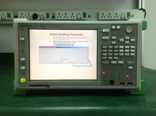
Anritsu MP1590B Network Performance Tester w/ MU150101A x1, OPT:02/03,PDH, DSn
Keysight/Agilent/HP 8703A Lightwave Component Analyzer Opt: 012 100,130MHz-20GHz
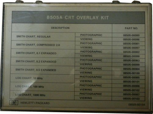
HP 8505A DISPLAY CRT OVERLAY KIT 08505-60154 SMITH LOG CHART GENUINE PART! SEE
PENNWALT 62A-2C-0125 PRESSURE GAUGE *NEW IN BOX*
Hewlett Packard Agilent 8720B 20GHz Network Analyzer with Options 001 & 010
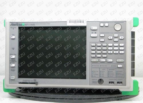
Anritsu MP1590B - 02 - 03 Network Performance Tester
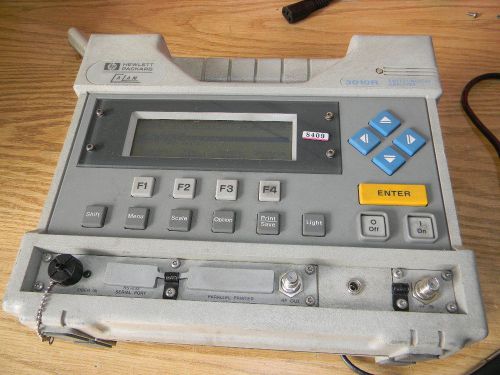
HP 3010R Sweep/Ingress Analyzer Model 85962A, Options 20 28 ABL
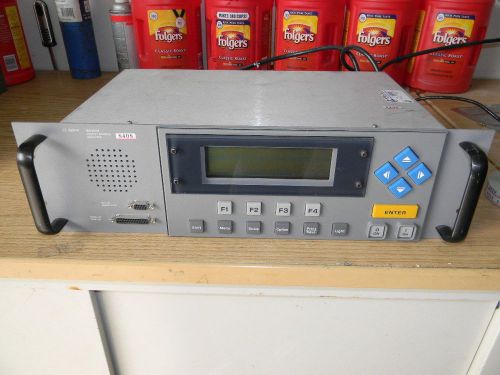
Agilent 3010H Sweep / Ingress Analyzer Model 85963A, Options ABA
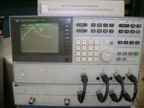
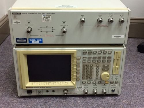
HP 3577A NETWORK ANALYZER W/ HP35677A S-PARAMETER TEST SET W/ MANUALS
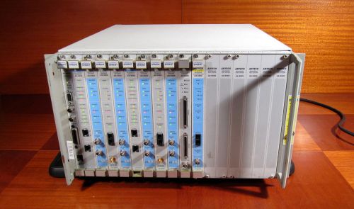
Adtech Spirent Netcom AX 4000 Broadband Test System with 11 Modules
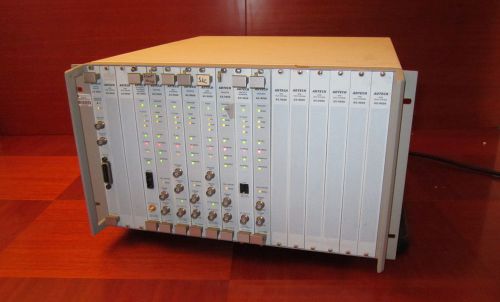
Adtech AX/4000 ATM Test System with Modules 400503A 400305 400500 400302 400310
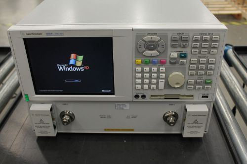
Keysight E8363B PNA Network Analyzer 40 GHz (Agilent E8363B)
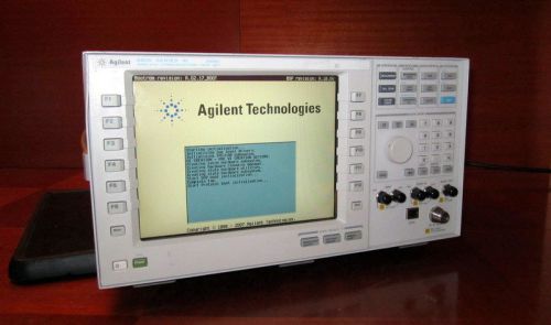
Agilent E5515C Wireless Communications Test Set Opt 003, HP 8960 Series 10
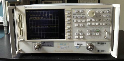
Agilent/HP 8719D Microwave Vector Network Analyzer 50MHz - 13.5GHz, Fully Tested
Anritsu MD6430A/MU643000B Handheld TouchScreen Network Datacom Interface and Da
People who viewed this item also vieved
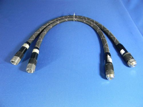
Anritsu/Wiltron 3671K50-1 High Frequency Flex Cables (SET) 30 Day Warranty
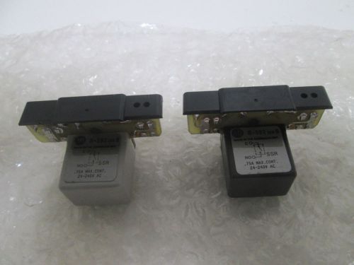
LOT OF 2 ALLEN BRADLEY 8-592 SER B PLUG IN MODULE *USED*
CV-8GFC-S4 4 port Fibre Channel card, STC Only
ICG3 ICG-3001BF Spirent Abacus 5000
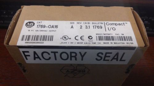
ALLEN BRADLEY 1769-OA16 SERIES A 16 POINT MODULE 240VAC *FACTORY SEALED*
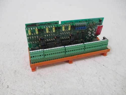
EAE SWA4 FIELDBUS I/O EXTENSION MODULE *NEW OUT OF A BOX*
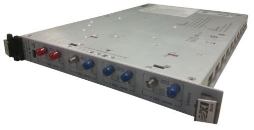
Agilent E4832A 675MHz w/ 4 x E4838A Generator front-end plug-in cards
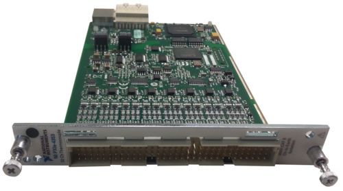
NI PXIe-4353 32-Channel, 24-Bit, Thermocouple Input Module
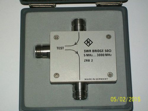
RHODE ROHDE SCHWARZ R&S ZRB2 3000 mhz 50 ohm SWR bridge HIGH DIRECTIVITY option
By clicking "Accept All Cookies", you agree to the storing of cookies on your device to enhance site navigation, analyze site usage, and assist in our marketing efforts.
Accept All Cookies