US $290
Directions
Similar products from Other Measurement Instruments
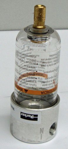
Parker Watts Minature Filter F504-01AHX11 12529EL
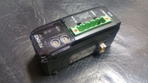
NEW KEYENCE Communication module DL-DN1 --FREE SHIPPING FROM USA--
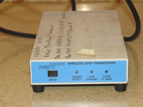
FREEWAVE WIRELESS DATA TRANSCEIVER MODEL DGR-115H (BB)
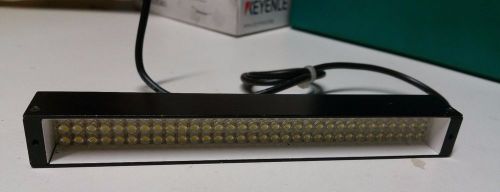
Keyence CA-dbw13 Backlight 7f09142 --FREE SHIPPING--
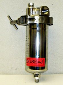
New Pall Max Pressure 150PSI Part-MLL4463G4EH13 14502ELS
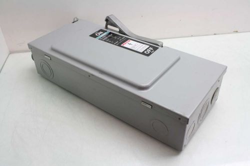
Siemens JU323 Enclosed Disconnect Switch / Type 1 Enclosure / 3 Phase
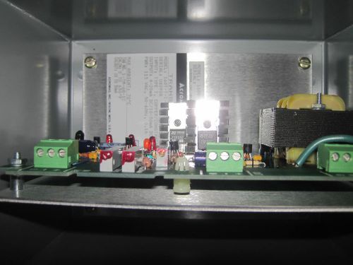
NEW Acromag 160T-T-I-U-I-C Transmitter IN NICE HOFFMAN U.L. ENCLOSURE TYPE 4
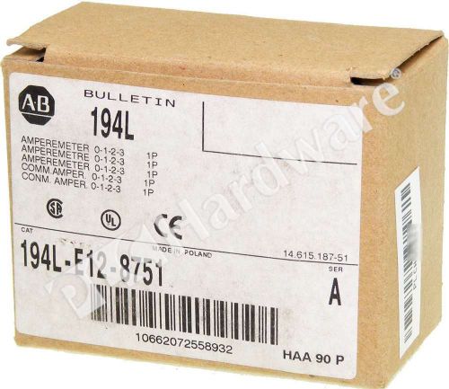
New Allen Bradley 194L-E12-8751 /A IEC Control and Load Switch 1 Pole 12A Qty
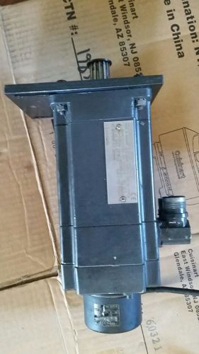
Brushless Siemens Motor & Encoder for Emco 1FT5042-OAK71-1-Z ID#295 434-NA
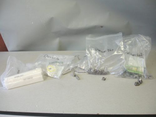
EG&G Spectrum Manufacturing CAM-Knurled Gripper More
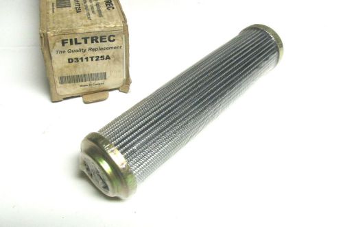
NIB .. FILTREC Replacement Filters Cat# D311T25A ... VI-70
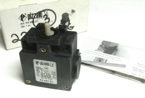
NIB .. PIZZATO Cat# FX 692-D1 ... VI-72
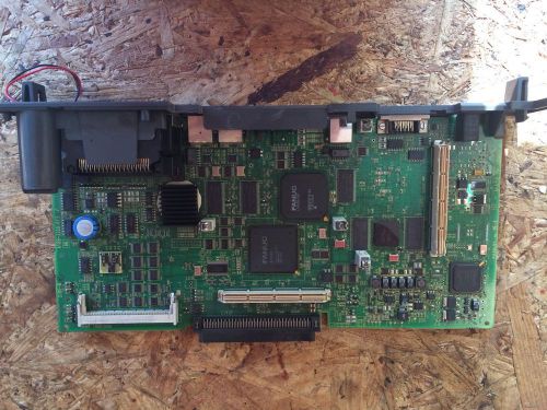
Used FANUC Board A16B 3200 0730 /05A
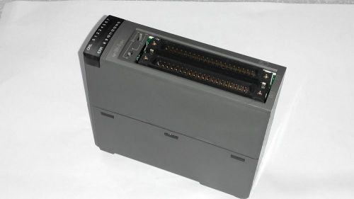
FUJI ELECTRIC I/O MODULE NP1W6406T 12-24VDC 0.12A 0.12 AMP A
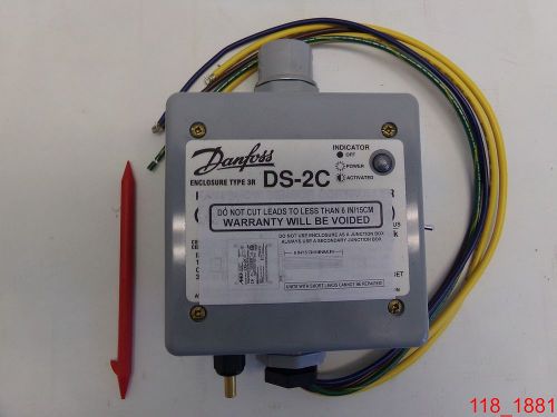
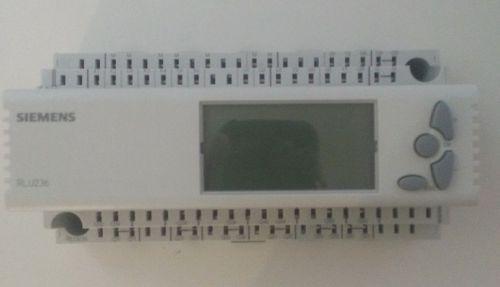
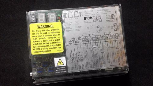
Danfoss DS-2C Rain/Snow Sensor Controller Type 3R
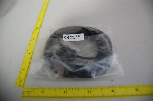
NEW PANASONIC PHOTOELECTRIC SENSOR PN:PM-L44P
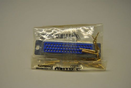
NEW AMPHENOL 50 PIN MALE D SUB CONNECTOR PN: 17-20500-1
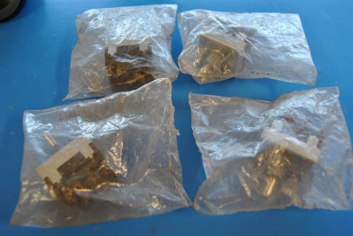
NEW (LOT OF 4) MCGILL 4 POLE TOGGLE SWITCHES 0140-4014
People who viewed this item also vieved
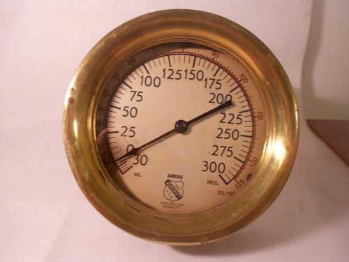
VINTAGE ANTIQUE BRASS ASHCROFT PRESSURE GAUGE Railroad Steampunk Vac Ammonia
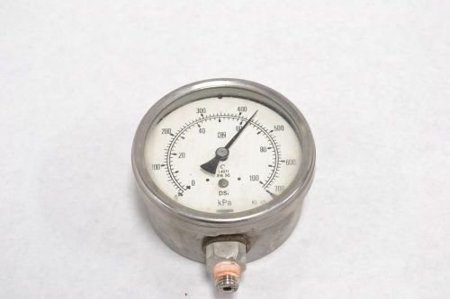
BOURDON PRESSURE 0-100PSI 4 IN 1/4 IN NPT GAUGE B302778
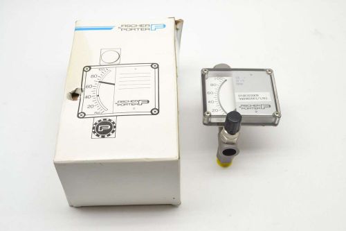
NEW FISCHER PORTER D10A3220CN FLOW 3 IN 1/4 IN NPT GAUGE B402333
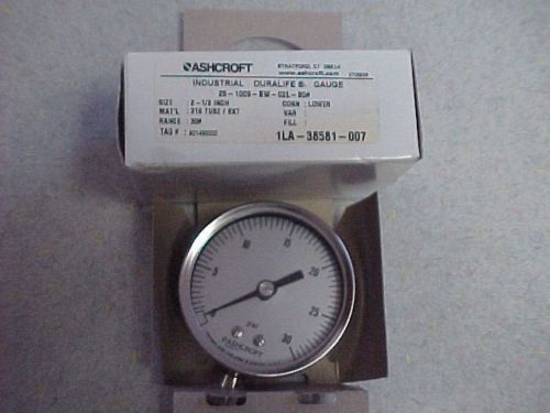
*NEW* ASHCROFT 2-1/2" INDUSTRIAL DURALIFE PRESSURE GAUGE 1LA-38581-007
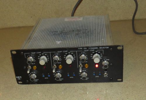
MKS TYPE 274 3 CHANNEL SELECTOR -gg
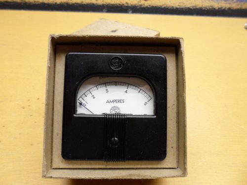
Vintage RCA-Simpson 0-5 amperes Meter Model#37
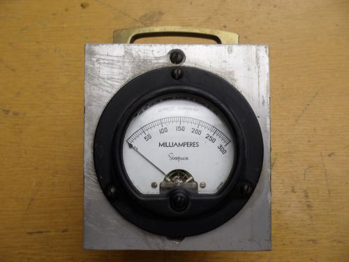
Vintage Simpson 0-300 Milliamperes Meter in steel box
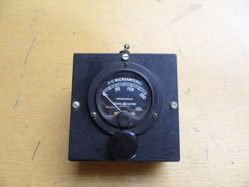
Vintage Box W/Switches & GE 0-150 DC Micro Amperes Meter,Model#ARE32-1
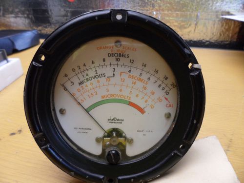
Vintage Phastron 0-20 Decibels,0-10 Micro volts Panel Meter
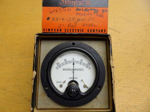
Vintage NIB Weston 25-0-25 Microamperes Meter model#566
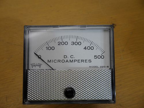
Vintage Triplet 0-500 D.C. Microamperes Panel Meter
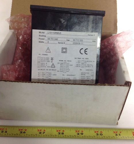
LAUREL 95240VAC 90-300VDC VOLTAGE METER SER.2 NIB L10110RMV5
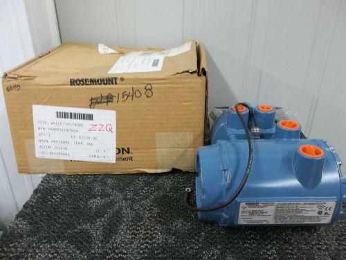
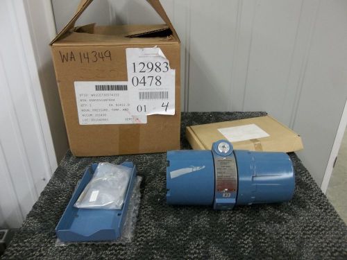
ROSEMOUNT SMART FAMILY HART PRESSURE TRANSMITTER 8732CR12N0M4T1 8732C NEW
ROSEMOUNT ANALYTICAL TEO WIRE TRANSMITTER 2081 PH NEW
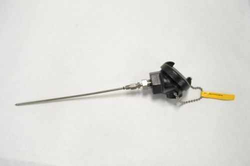
B&B INSTRUMENTS 038E-012-01A-9HP34 10IN PROBE TEMPERATURE TRANSMITTER B202305
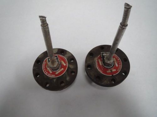
LOT 2 AMETEK SJ TYPE PRESSURE TRANSMITTER DIAPHRAGHM SEAL 2000PSI B202294
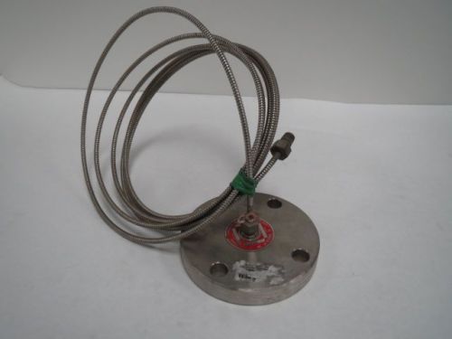
ZAVODA T630-51 TRASMITTER DIAPHRAGM TEFLON MOUNTING KIT B202271
BAILEY BCN56211150 13-42V-DC 0-100PSI PRESSURE TRANSMITTER B401543
FOXBORO PT-1010 5/8IN SHAFT POSITION 427 TURNS TRANSMITTER B202255
By clicking "Accept All Cookies", you agree to the storing of cookies on your device to enhance site navigation, analyze site usage, and assist in our marketing efforts.
Accept All Cookies