US $1,560.00
| Condition: |
New: A brand-new, unused, unopened, undamaged item in its original packaging (where packaging is
applicable). Packaging should be the same as what is found in a retail store, unless the item was packaged by the manufacturer in non-retail packaging, such as an unprinted box or plastic bag. See the seller's listing for full details.
...
|
Brand | Instek |
| MPN | MDO-2204EX | ||
| Model | MDO-2204EX |
Directions
Similar products from Portable & Digital Oscilloscopes
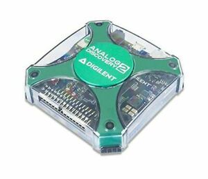
Digilent Analog Discovery 2: Digial Oscilloscope Logic Analyzer and Digital Patt
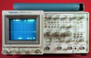
Tektronix 2467B 4-Channel 400MHz High Writing Speed Oscilloscope
Tektronix TDS 820 Dual Channel Digitizing Oscilloscope 6GHz, ±6V, 14-Bit, GPIB
EZ Digital OS-5060A Oscilloscope
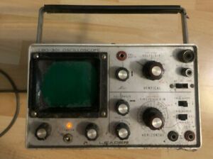
Leader Electronics Oscilloscope LBO-301
IWATSU SS-5702 OSCILLOSCOPE DC - 20 MHZ
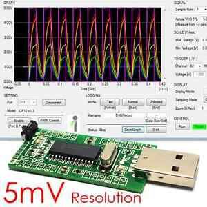
Promo! iCP12 (5mV)- 6 Ch. PC Analog USB Oscilloscope Unlimited Logger IO DAQ ADC
Vintage -Beckman -Circuitmate 9020 - 20 Mhz. Oscilloscope

TEKTRONIX 2214 OSCILLOSCOPE OPERATORS MAUAL
TEKTRONIX TEK 545 OSCILLOSCOPE CRT 154-0175
Tektronix TDS1002B 60 MHz Dual Channel Digital Oscilloscope Lab
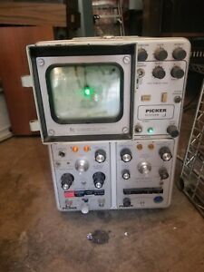
OSCILLOSCOPE TYPE 564B PICKER ECHOVIEW STORAGE OSCILLOSCOPE
Tektronix Oscilloscope Camera # C-27
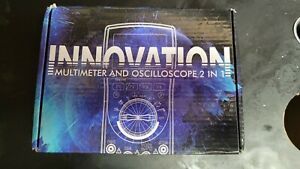
MUSTOOL MDS8207 MULTIMETER and OSCILLOSCOPE 2 in 1
Tektronix TDS 2004B Four-Channel Digital Storage Oscilloscope
Tektronix TDS 2004B 4-Channel Digital Storage Oscilloscope
Digilent Analog Discovery 2: Digial Oscilloscope Logic Analyzer and Digital Patt

TEK Gets Visible Results,Tektronix,Coffee,Tea,Cup,Mug,Oscilloscopes,Beaverton,OR
RIGOL DS1052E Oscilloscope 2 Channel 50 MHz - White
Telequipment D61a Oscilloscope
People who viewed this item also vieved

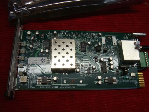
MA-COM MA7J-RX RECEIVER RF FREQ 6600.00 XTAL 102.0313
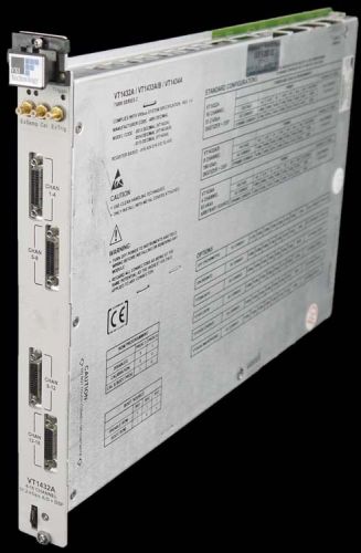
VXI Technology VT1432A 16-Channel 51.2kSa/s Digitizer +DSP Plug-In Module C-Size
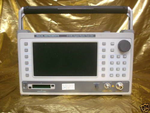
Racal Dana 6103E Cellular Phone Test 01 02 10 53 04F
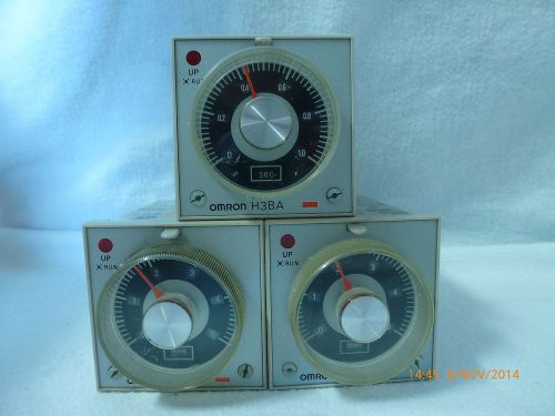
Omron H3BA-8H Timer 200-240VAC 50-60Hz 5A 250VAC 8pin Qty 3 Good Condition
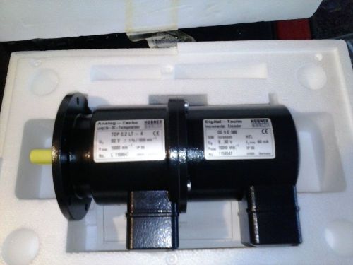
Hubner Baumer Longlasting DC analog digital Tachometer w/encoder
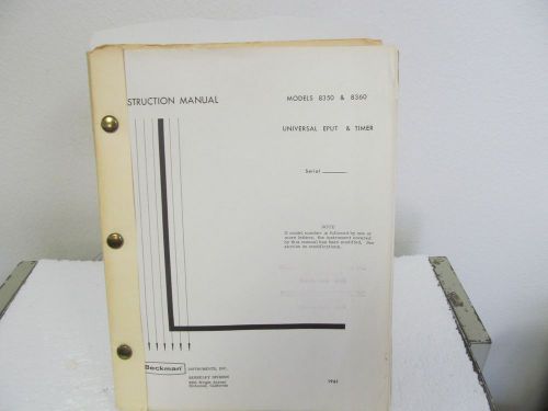
Beckman (Berkeley Div.) 8350, 8360 Universal EPUT & Timer Instruction Manual
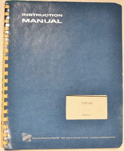
VINTAGE '68 INST MANUAL MODIFICATION INSTERT - TYPE 602 OPTION 1 TECTRONIX INSTR
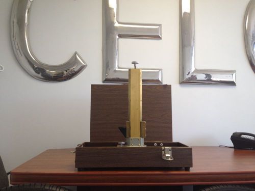
X-Y TRAVERSES CELCO C1981 ( 10" x 10" )
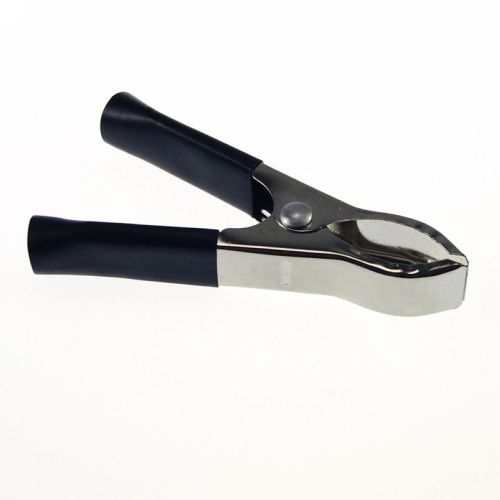
(10) Soft Plastic Boots Metal Car Battery Clip Clamps Alligator Clamps 20A
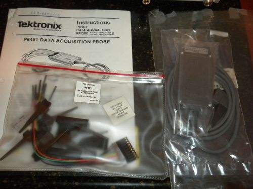
Tektronix Data Acquisition Probe P6451
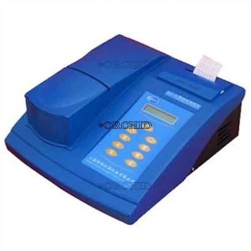
TURBIDITY METER NEW RS232 MICROCOMPUTER WGZ-2000 TURBIDIMETER BACKLIGHT LCD
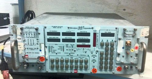
Microdyne Telemetry Reciever Model 1200-MR
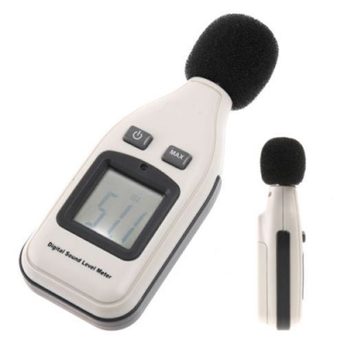
LCD Digital Sound Noise 30-130dB Level Meter Measure Decibel Pressure Tester New
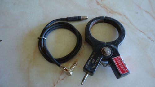
DYNATEL 300 DYNA-COUPLER AND CABLE FOR USE WITH DYNATEL 573 CABLE LOCATOR
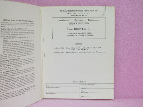
Honeywell Manual Cam-Type Program Controller Thermometer Meas. Sys. Instr. Man.
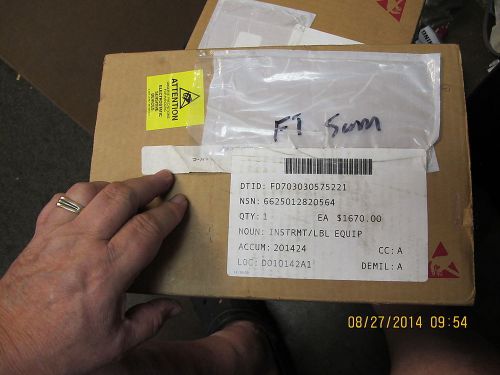
TRACK MICROWAVE MICROPROCESSOR ASSEMBLY 11165-8421-6 TIMING SYSTEM 662501280564
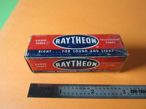
VACUUM TUBE RAYTHEON 6S4 RECEIVER TV RADIO BIN#D6
By clicking "Accept All Cookies", you agree to the storing of cookies on your device to enhance site navigation, analyze site usage, and assist in our marketing efforts.
Accept All Cookies