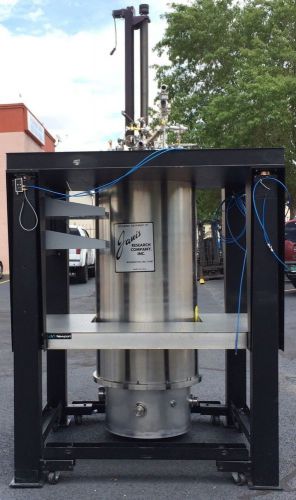


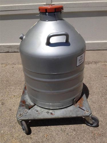
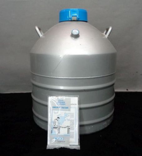
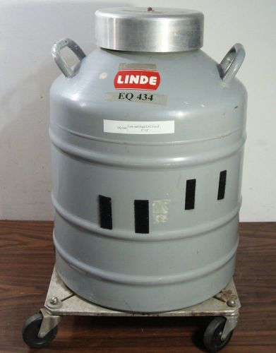
US $2900
| Condition | Used
:
An item that has been used previously. The item may have some signs of cosmetic wear, but is fully operational and functions as intended. This item may be a floor model or store return that has been used. See the seller’s listing for full details and description of any imperfections.
|
| Seller Notes | “Very Good. See Description.” |
Directions
Similar products from Cryogenic Tanks & Accessories
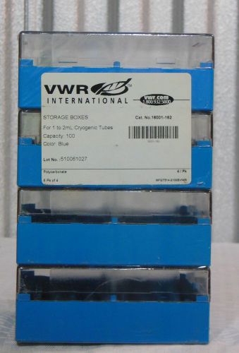
VWR 16001-162 1-2mL CryoPro Cryogenic Vial Storage Boxes capacity: 100 x4 racks
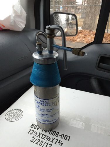
BRYMILL CYROGENIC SYSTEMS MINI CRYOGUN LIQUID NITROGEN LN2 CRY-AC LOW RESERVE!!!
VWR 25000-136 7.6cm (3") Storage Box with 81-Cell Divider 820003 39 boxes
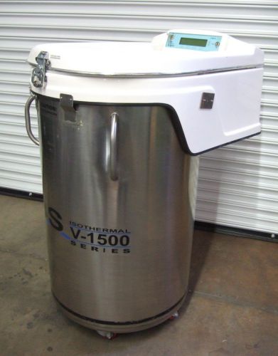
CBS Isothermal V-1500 Cryo Liquid Nitrogen Biogenic Tank Dewar Freezer CBS 2300
Cryomed Model 910-A 910A Freezing Chamber with Racks CRYOGENICS $199
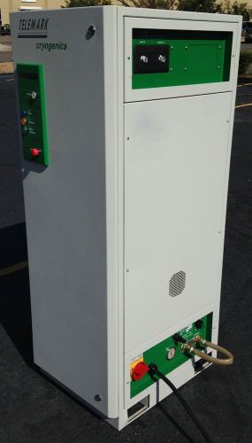
Telemark Cryogenics Water Vapor Crotrap * TVP-2000 * 2000 W Max Load * Nice
Nalgene Catalog Number 5115-0012 Labtop Cooler Jr.
MVE CRYO BIOLOGICAL TANK 8 CANISTER HighCapacity Refrigerators Series Cryogenic
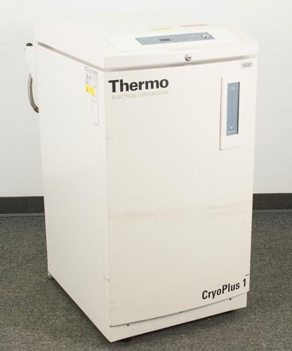
Thermo Electron CryoPlus 1 7400 Liquid Nitrogen Freezer -USED
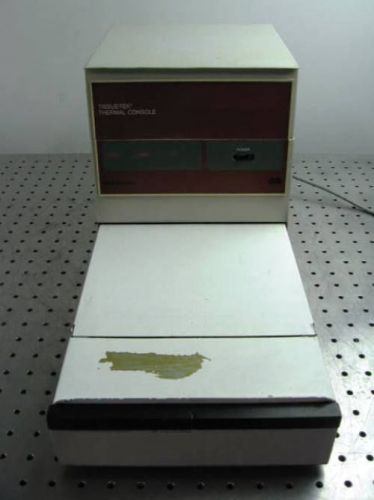
G110236 Miles Scientific 4585 Tissue-Tek Thermal Console
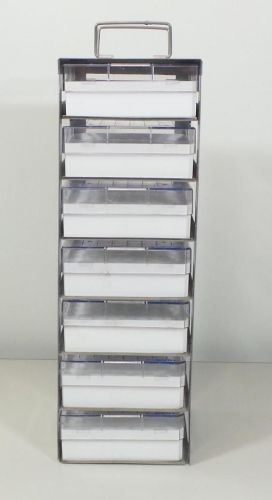
Lot of 4 Cryogenic Freezer Storage Racks +7x Nalgene Polycarbonate Storage Box
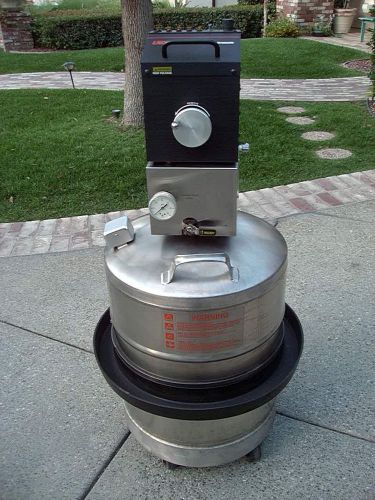
TA INSTRUMENTS LNCA LIQUID NITROGEN COOLING CRYO UNIT
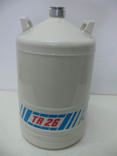
Air Liquide TR26 Liquid Nitrogen Tank, Dewar Canister Tank
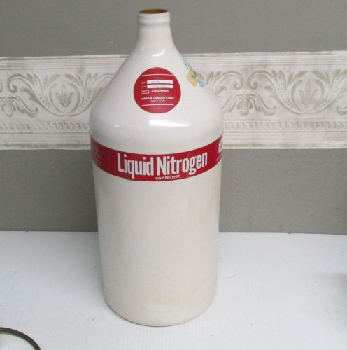
Union Carbide Cryogenics Products Liquid Nitrogen Tank UC-4
MVE Cryogenics MACH SM-43 Liquid Nitrogen Storage Tank-EX! NR!
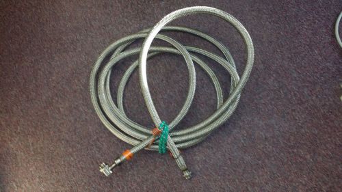
Cryogenic Hose 19 Ft Long Stainless Steel
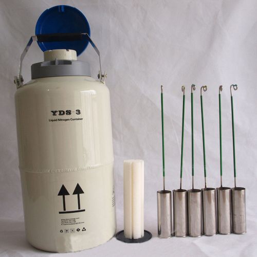
STON New 3.15 L Cryogenic Container Liquid Nitrogen Tank with Straps Portable
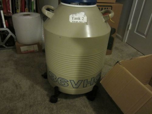
Taylor Wharton 36VHC Liquid Nitrogen Cryogenic Chamber Lab Container not 35vhc
LINDE UNION CARBIDE LR-30 LIQUID NITROGEN CRYOGENIC CRYO TANK DEWAR + CANISTERS
People who viewed this item also vieved
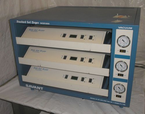
SAVANT GDS300-230 STACKED GEL DRYER SGD300
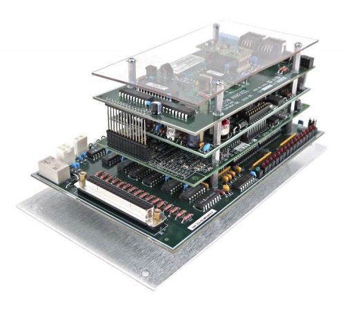
Lam Research Watlow Anafaze 778-9000046-403 Lon Com Card PCB Assembly w/Cables
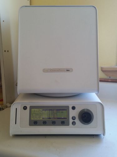
Ney CeramPress Qex Porcelain and Pressing Furnace
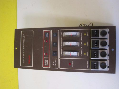
TYLAN 3 ZONE FURNACE CONTROLLER CONTROL BOAT RARE USED 30 DAY GUARANTEE
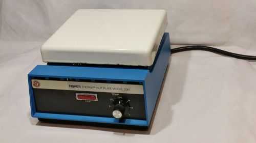
Fisher Thermix Hot Plate Model 200T
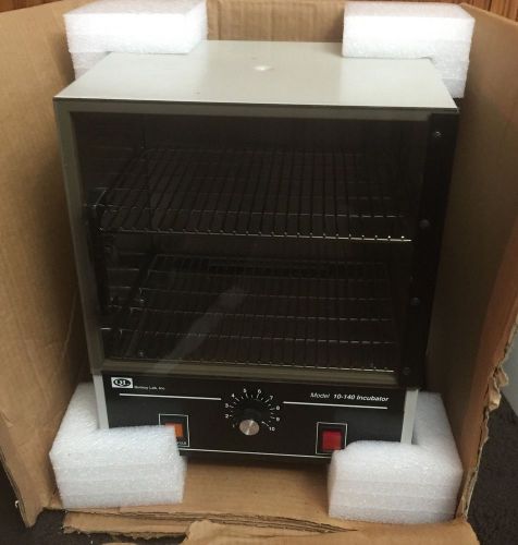
Quincy Lab Incubator Model 10-140
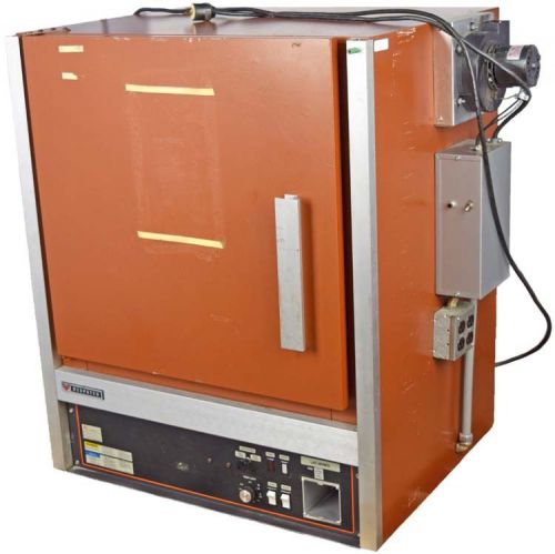
Despatch LAC1-67 260C/500F 240V 11.6A 1-Phase 2400W Lab Benchtop Oven PARTS
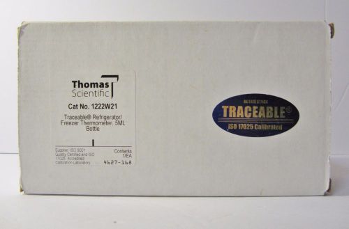
Traceable® Refrigerator / Freezer Plus™ Thermometer With 5 ML Bottle 1222W21
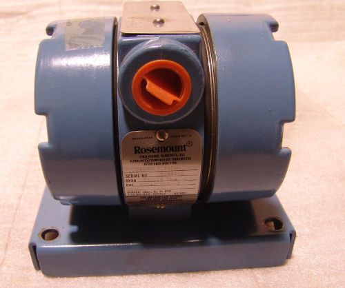
Rosemount temperature transmitter 0444RL2U1A2NA needs repair
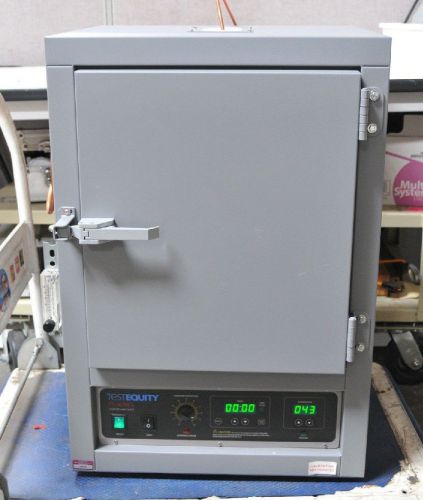
Test Equity FS2-1 FS Series Forced Air Oven 1.55 Cu Ft, 120 V Input
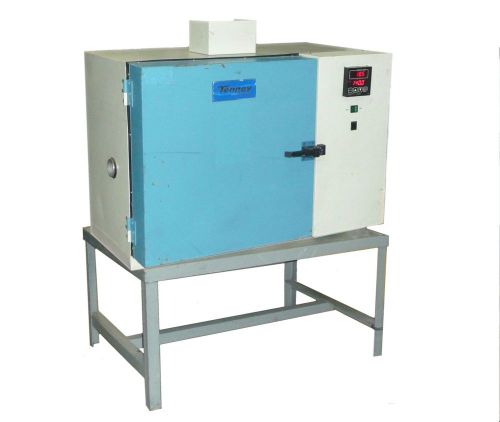
TENNEY TJR LAB TEMP TEMPERATURE ENVIRONMENTAL TEST CHAMBER OVEN -75C to 200C
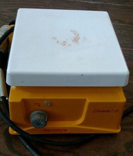
Thermolyne Cimarec 2 Hot Plate 7.5" x 7.5" HP46825, working
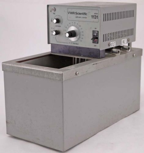
VWR Scientific 1131 Laboratory Desktop Adjustable Heated Circulating Water Bath
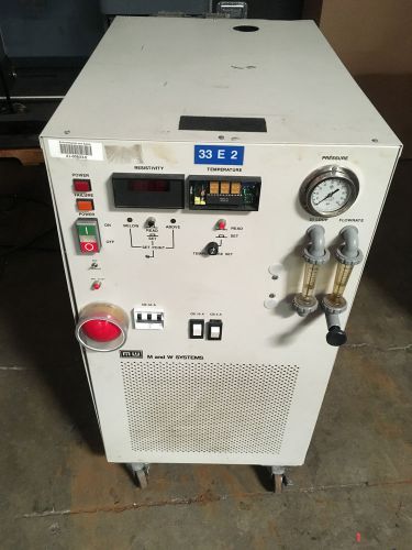
M and W Systems Flowrite Recirculating Cooling System RPCX28A-D-DT-DI2x10"
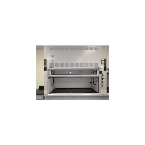
Fisher Hamilton SafeAire 6' Bench-top Fume Hood Series No. 60L
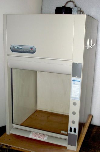
Labconco Protector Fume Hood Cat. No. 3030004 with Blower & Light; Wrnty

5000 ML / 5 Ltr Capacity,110 V, Aluminium Heating Mantle for Flask BASCO 02
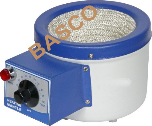
5000 ML / 5 Ltr Capacity,110 V, Aluminium Heating Mantle for Flask BASCO 01
By clicking "Accept All Cookies", you agree to the storing of cookies on your device to enhance site navigation, analyze site usage, and assist in our marketing efforts.
Accept All Cookies