


US $1,245.00
| Condition: |
Seller refurbished: An item that has been restored to working order by the eBay seller or a third party not approved by
the manufacturer. This means the item has been inspected, cleaned, and repaired to full working order and is in excellent condition. This item may or may not be in original packaging. See the seller’s listing for full details.
...
|
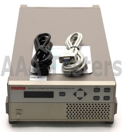
Brand | Keithley |
| Model | 2306 |
Directions
Similar products from Optical Power Meters, Fault Locators & Testers
EigenLight 310-20 Power Monitor W/ Accessories & Operating Instructions
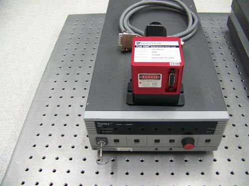
NEW FOCUS ECDL VORTEX 6000 TLM7000 780.240 nm Laser
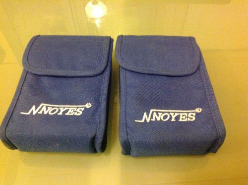
Noyes/AFL Telecomunications Power Meter OPM4 & Optical Light Source OLS1 Combo
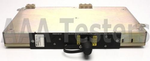
GN NETTEST CMA4425 SM OTDR Module 4 CMA 4000 4000i 4425 CMA4000 CMA4000i
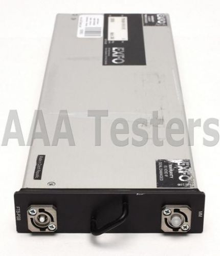
EXFO FTB-PSB Stand Alone MM Fiber Pulse Suppressor Box
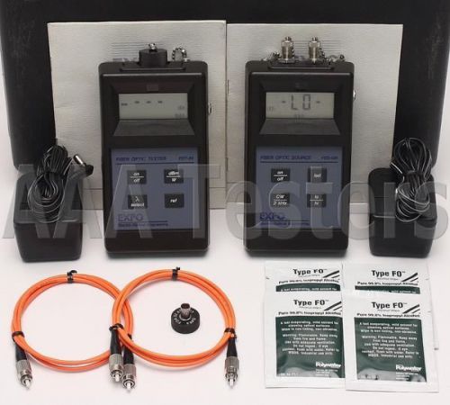
EXFO FOS-120 FOT-22 MM Fiber Optic Loss Test Set FOT 22 FOS-124-32 FOS FOT
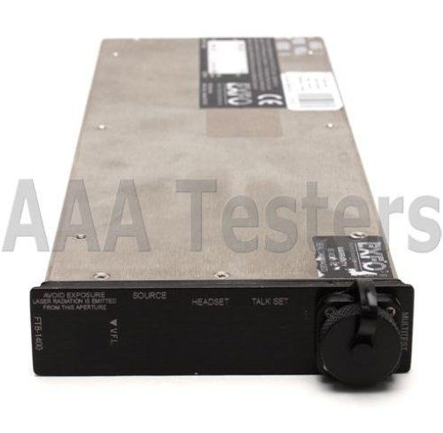
EXFO FTB-1402 MultiTest Module FTB-1400 w/ Power Meter 4 FTB-400 FTB400 FTB 1400
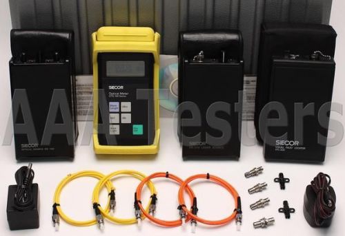
Siecor Corning OTS-100 SM MM Fiber Loss Test Set w/ VFL OTS-110 OS-210XD OS-100D
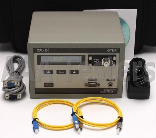
Noyes OFL-100 LR SM 1310nm Fiber Optic OTDR OFL100 OFL 100
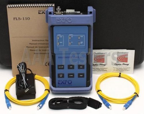
EXFO FLS-110 Polarized Singlemode Optical Light Source 4 PMD Testing FLS 110
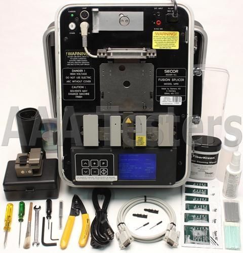
Siecor Corning M90 4000 SM MM Fiber Core Alignment Fusion Splicer w/ Cleaver
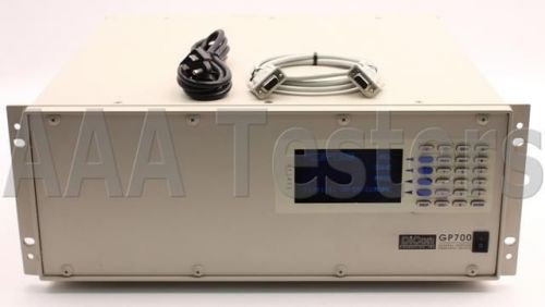
DiCon GP700 General Purpose Fiber Optic Switch Platform GP-700 GP 700
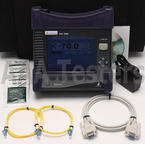
Acterna JDSU OFI2000 SM Fiber Optic Loss Test w/ VFL & ORL OFI-2000 OFI 2042
Infrared solutions, flir, flexcam Pro
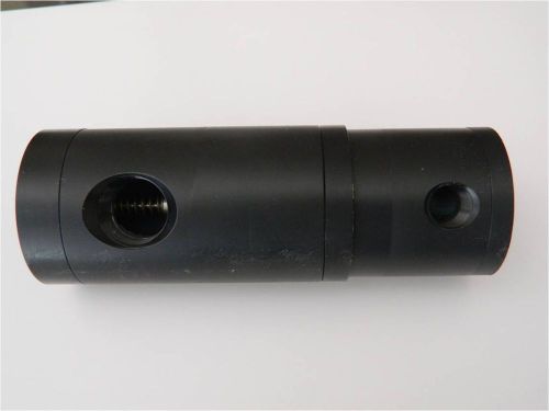
Coherent Antares laser temperature control valve
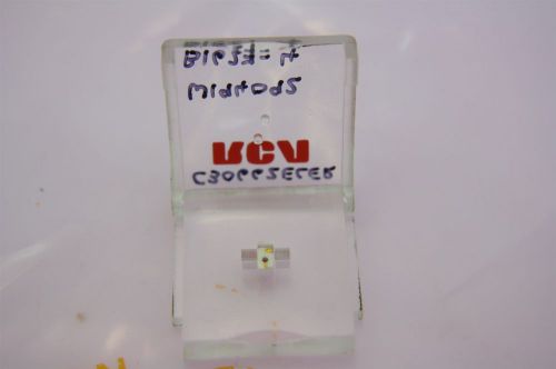
PerkinElmer InGaAs Avalanche Photodiode C30662ECER Ceramic OTDR
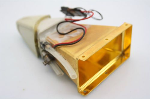
Light Funnel Gold Coated 1 TO 15 Magnification With Cooling Magnifying Laser Tip
EPN-25 PON Optical Power Meter 1310/1490/1550nm, PON Power Meter
Fluke Ti100 Thermal Imager 9Hz
People who viewed this item also vieved
PCB PIEZOTRONICS 462A CHARGE AMPLIFIER for ACCELEROMETER VIBRATION CALIBRATION
HP E1460A 64 CHANNEL RELAY MODULE
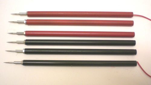
Vintage H.H. SMITH, 3 RED, 3 BLACK,Special Needle Point Probes, Extra Long, USA
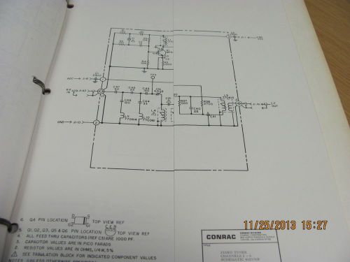
CONRAC MANUAL 1000 Series: Audio/Video Receiver - Install&Operating schems 19242
High precise thermometer Mini Digital LCD Display Infrared Thermometer GOOD OR
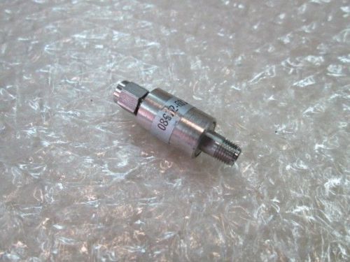
HP Agilent 08672-60187 ATTENUATOR-SMA COAX FOR 8672A
PULSE COUNTER MICROPROCESSOR BASED 220V AC 50 Hz
6pcs Alligator Clip to 4mm Banana Jack Female Insulate Clamp Adapter Red Black
Tektronix 7A19 Amplifier Instruction Manual
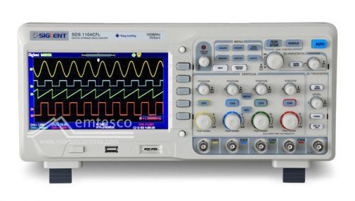
Siglent SDS1104CFL 100MHz 4CH 1GSa/s (per CH) 7" Screen
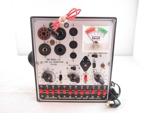
EMC Model 215 Tube & Transistor Tester Complete Box Very Good Cosmetic Condition
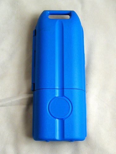
Det-tronics Gas Calibration Kit Carrying Case Only for Methane or H2S
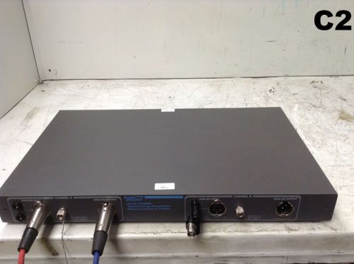
Audio Precision AUX-0025 Switching Amplifier Measurement Filter
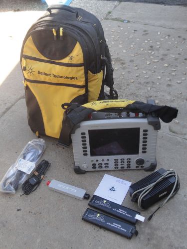
HP Agilent E7495 Base Station Test W/ 200 210 220 510 600 700 Meter Analyzer
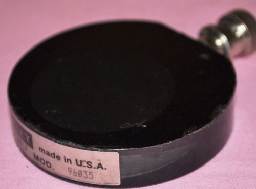
Keithley Model 96035 Lon Chamber SN 50014
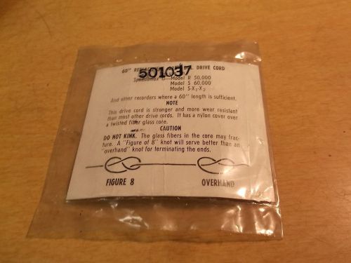
NEW 60" Replacement .023" Diam Drive Cord Speedomax C R50 S60 *FREE SHIPPING*
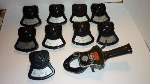
Vintage Columbia Electric Co. Tong-Test Amperes Model Large Piece Set & Box
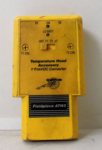
Fieldpiece ATH3 Temperature Head Accessory Dual Temperature 8503D Yellow
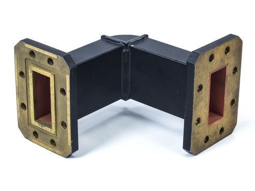
Lieder Development 90 Degree Waveguide Assembly Connector (T2-B-1)
By clicking "Accept All Cookies", you agree to the storing of cookies on your device to enhance site navigation, analyze site usage, and assist in our marketing efforts.
Accept All Cookies