US $12.95
| Condition: |
Brand New: A new, unread, unused book in perfect condition with no missing or damaged pages. See the seller’s
listing for full details.
...
|
Brand | Kohler |
| Model | 20-300 kW |
Directions
Similar products from Generator Parts & Accessories
GENERATOR GASONLINE CHICAGO ELEC PWR TOOLS 6 KW 11 HP 120V/240V
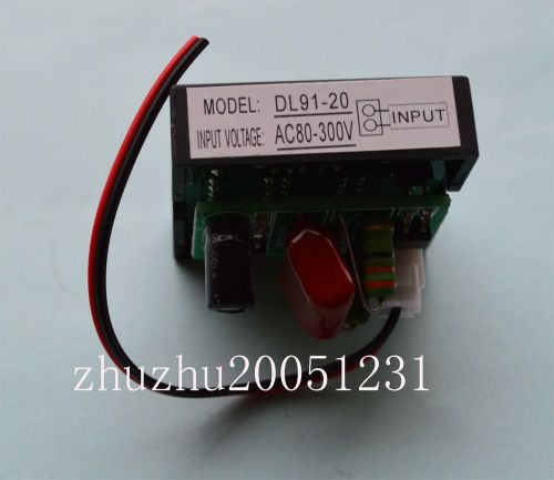
2PC New Useful AC80-300V Generator Digital Voltage red Led Meter Gauge DL91-20
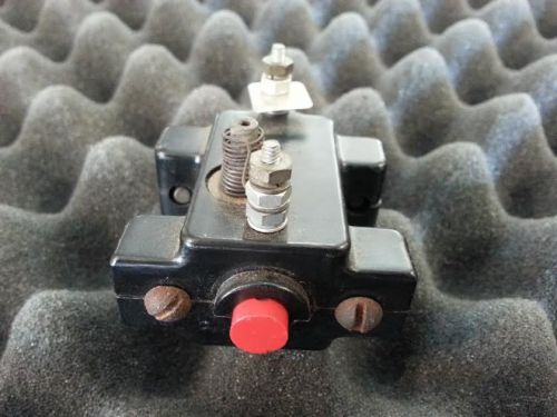
KOHLER 243026 / ONAN 320-0104 SWITCH
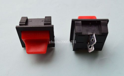
2pcs 2Pin Red Button 2-6.5KW 4 Light Lamp On-Off DPST Rocker Switch Brand new
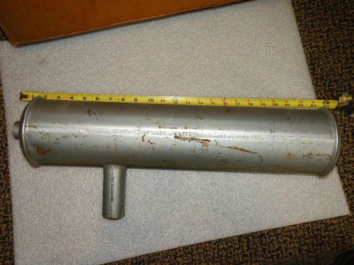
ONAN GENERATOR NELSON MUFFLER NOS 4.0 BFA-16004-C OLD STOCK PART
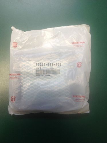
Honda Air Cleaner Element Part #17211-ZS9-A02
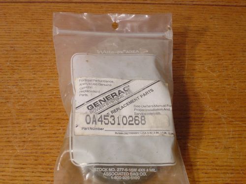
GENERAC GENERATOR IGNITER KIT DISTR. PART # 0A45310268

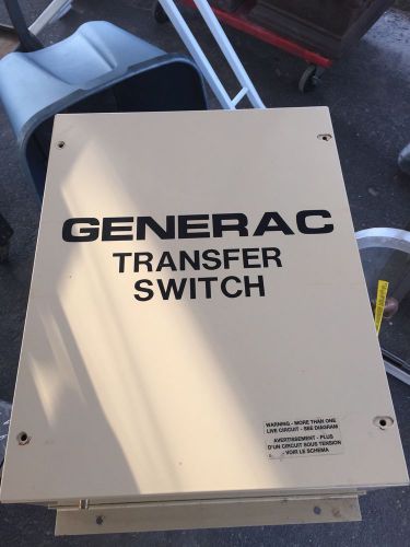
Generac Transfer Switch # 0046782
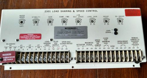
Woodward 2301 Load Sharing and Speed Control P/N 8271-442
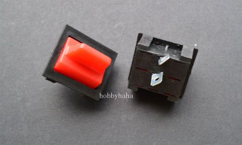
2pcs Brand new 2Pin Red Button 2-6.5KW 4 Light Lamp On-Off DPST Rocker Switch
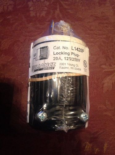
RELIANCE CONTROLS L1420P 20A 125/250VGenerator Power Cord Plug (5000w) 4 Prong
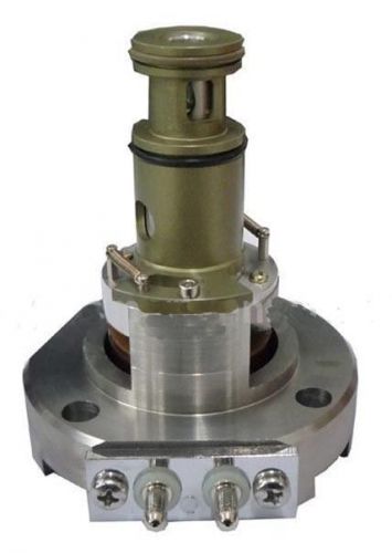
Engine Actuator 3408328, 0-500kw Low-flow open form diesel parts 24V

1pcs 5kw New Gasonline Petrol Generator 188 190 Ignition Key Switch 6 Wire key
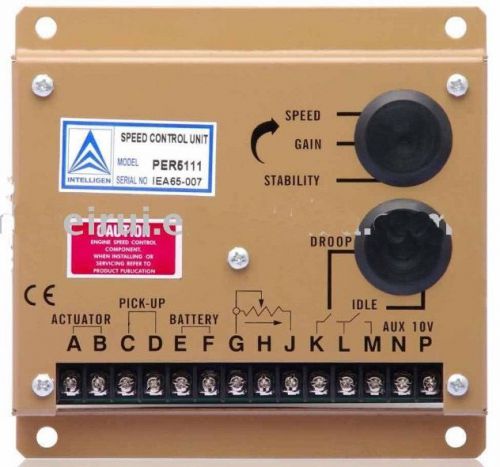
5111 Electronic Engine Speed Controller/governor for generator/Genset parts

1pc 5kw Gasonline Petrol Generator F188 F190 Ignition Key Switch 6 Wire key New
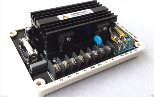
General Universal Automatic voltage regulator AVR EA16 Generator/Genset part
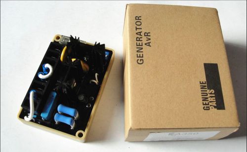
NEW Automatic Voltage Regulator AVR EA350
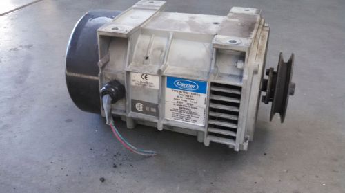
5.0 KVA 240 Volt Generator Head 20.8 Amp Carrier defrost
People who viewed this item also vieved

TRACTEL BRAVO 3000KG 3 TON LEVER CHAIN HOIST YEAR 2009 VAT INCLUDED

35mm Ferrules Tube End Caps Walking Stick Ferrule Chair Feet Black Rubber x4
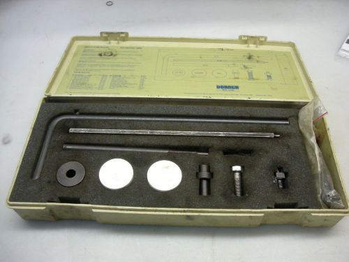
Dorner 4100 Series Tool Kit Part #4500 - Missing Bearing Puller #45-05A

Spring Hammer with Depth Gauge Delta Kits
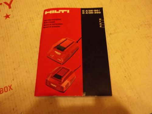
HILTI C 4/36/90--C4/36/350 BATTERY CHARGER *Paper Manual Only*

1 -24" x 4' RENOVATED Steel Ply Concrete Wall Form Panel
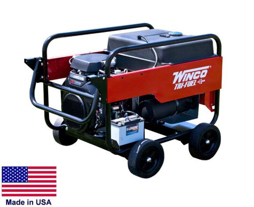
PORTABLE GENERATOR Tri Fuel - 12,000 Watt - 120/240V - 21 Hp Honda - Elect Start
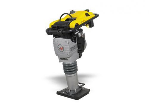
Wacker Neuson BS50-2i (oil Injected) 2-cycle engine 715 BPM Rammer Jumping Jack
Hilti .27 cal Short #50354 Cal. 6.8/11 M Black Shot (Lot of 100)
Case Agriculture Mechanics Magnetic Parts Tray NIB Red Power Products 9 X 5"
NEW GREENLEE 38456 SB SLUG BUSTER HYDRAULIC 3' HOSE for KNOCKOUT PUNCH SET 1/2-4
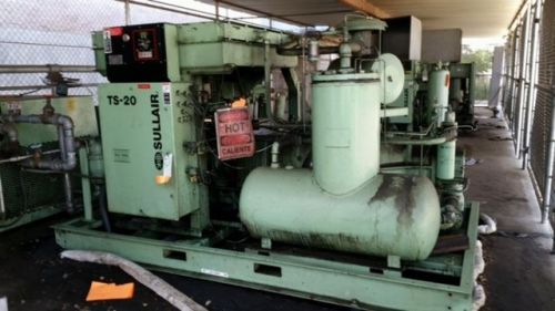
Sullair TS-20 100 HP Air Compressor / Two-Stage Air End
MASTER 120V 14.5A 60HZ HEAT GUN HG-751 B
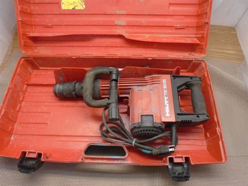
HILTI TE 805, Breaker performance W/ Case, 120v Breaker Grounded, USED
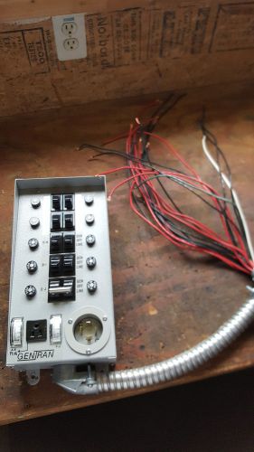
GENTRAN 10 Circuit Generator Transfer Switch. Model 30310 30 Amp.
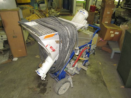
M-TEC MONO-MIX FU CONCRETE MIXER PUMP 230V 60Hz 290PSI 20A W/ACCESSORIES *XLNT*
By clicking "Accept All Cookies", you agree to the storing of cookies on your device to enhance site navigation, analyze site usage, and assist in our marketing efforts.
Accept All Cookies