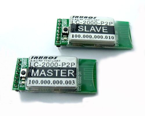
2016041201324766460 2016041201324766460 Best-ego LC-2000-P2P 2.4G RF Module UART 115Kbps RF UART TTM RS-232 For Arduino STM32 ARM Features 1, Low Cost , easy to use , zero RF knowledge request for wireless communication design. 2, Transparent Transmission Mode (TTM), save MCU resource, implement wireless communication over the wired UART programming. 3, Per to Per communication (P2P) 4, Full duplex working , max support baud rate 512Kpbs. 5, Max continuous bi-direct baud rate up to 115Kbps. 6, DTR signal support used for Arduino for remote upload sketch. 7, Power Save Mode (PSM) current consumption down to. 8, Sleep mode current consumption down to 150uA. 9, LC-2000-P2P: 0dBm, Low power , 20 to 30m distance LC-2000PA-P2P: 20dBm , 200 to 300m distance The RF communication is very depended on it’s working environment, the distance is out door clear environment and only for reference. Pin Description Pin NO. Pin Name I/O Function Remark 1 VCC P Power supply, DC 3.3V 2 TXD O UART TXD 3 RXD I UART RXD 4 GND P Power Ground 5 FUN I PAIR/CONFIG Active LOW, Pull LOW and hold over 3 sec to enter PAIRING MODE 6 BUSY O Busy Status Indication Active LOW, Before sent data to TX pin , ensure BUSY pin is High 7 DTR * DTR signal, Used for Arduino Upload sketch The direction is :MASTER->Slave Master: INPUT Slave: OUTPUT Important Notes: The LC-2000(PA)-P2P serial module is working under per to per mode , a Pairs of LC-2000(PA)-P2P has contained two unis , one is MASTER and the other one is SLAVE, the module will mark it on it’s label. LC-2000(PA)-P2P Working Mode The LC-2000(PA)-P2P have below working modes: 1, Normal mode: In this mode, the module will be standby after power on , user can be sent or receive data at any time, this mode have least delay and highest power consumption, this mode can be used on minimum data delay request applications. 2, Power Save Mode (PSM): In this mode , module will be working on 10% proportion of intermittent mode, user can be sent data at anytime but other side maybe receive data a little bit delay , the delay time is depended on the working mode of receive side, the max delay time is 2sec. This mode only consumption 10% of power and also ensure the data transmission with a little bit delay. 3, Sleep Mode: In this mode , the module will stay in sleep mode , it will not sent or receive any data , user need to pull “FUN” pin low to wake up the module , and then send data , after data transmitted the module will be going to sleep mode again, this mode have minimum power consumption but user need to make application protocol to ensure communication ok. The module will be delivered with Normal mode , user can be switch the mode by config command. Pairing Before using the module , user need to pairing it , then the module can be communication to each other , to pairing the module , user need to notice beow: 1, Only one MASTER and one SLAVE can be pairing. 2, To Pairing the module , press and hold the “PAIRING” button one the moude , or pull the “FUN” pin low and hold it over 3sec , the module will be entry PAIRING mode , the LED will be flash to indication the status. 3, Do same thing on other side, once both module entry PAIRING mode , they will be pair very quickly and the LED will be OFF , that mean the module is paired and ready to communication to each other. 4, One MASTER only can paired with one SLAVE and the smae for SLAVE , that means if one module paired with a new module , the old paired module will be lost paired and they will not communication anymore. 5, To ensure the module was paired , pull low the DTR pin of MASTER side , the SLAVE side will be follow the status, please note that the DTR is unidirectional working , that means only the SLAVE’s DTR pin follow the MASTER ‘s DTR status. If you sent configuration command after pull low the FUN pin , the module will entry CONFIG mode , not PAIRING mode . Configuration Command If user to configuration the module , user need to pull “PAIR/CFG” pin low , module will be entry CONFIG mode , then sent configuration command via TXD , after configuration , pull “PAIR/CFG” pin high. The timing as below: In CONFIG mode , user can be sent command with any baud rate , the module will auto apply the baud rate , after exit the CONFIG mode , the module will apply baud rate as the configuration data (may be difference as the CONFIG mode). The configuration command is full text mode, the format as below: Fixed token: “=” Command Value: 3 digitals with ASCII character (Range 000 to 999) Fixed separators : “:” Parameter: max 240 ASCII character Fixed end symbol: “\r\n” For the example: MCU send command to LC-2000-P2P: =”800:\r\n” // Read local UID LC-2000-P2P reponce: =”=800:100.000.000.001\r\n” // This module’s UID is : 100.000.000.001 The detailed command list as below: No. Function Directional Fixed token Command Value Fixed separators Parameters Fixed end symbol 1 Set working mode MCU to Module = 902 : Working Mode: “0” : Normal Mode “1” : PSM Mode “2”: Sleep Mode \r\n Module to MCU = 902 : \r\n 2 Set PAIRING Mode MCU to Module = 902 : PAIRING Mode: “0” : Exit pairing Mode “1” : Entry pairing Mode \r\n Module to MCU = 902 : \r\n 3 Set Baud Rate The Baud rate config only used for Master side , the slave side will be follow the Master side automatic MCU to Module = 911 : Baud Rate (bps): 2400 4800 9600 14400 19200 38400 56000 57600 115200 128000 256000 512000 \r\n Module to MCU = 911 : \r\n 4 Read UID MCU to Module = 800 : \r\n Module to MCU = 800 : DDD.DDD.DDD.DDD (Local UID) \r\n 5 Read working mode MCU to Module = 801 : \r\n Module to MCU = 801 : Working Mode: “0” : Normal Mode “1” : PSM Mode “2”: Sleep Mode \r\n 6 Read baud rate MCU to Module = 801 : \r\n Module to MCU = 801 : Baud Rate (bps): 2400 4800 9600 14400 19200 38400 56000 57600 115200 128000 256000 512000 \r\n 7 Read Version number MCU to Module = 807 : \r\n Module to MCU = 807 : FW Version: FW (DDD,DDD), HW(DDD,DDD) Protocl Version (DDD,DDD) \r\n 8 Read paired other side UID MCU to Module = 804 : \r\n Module to MCU = 804 : DDD.DDD.DDD.DDD (Other side’s UID) \r\n Remote upload sketch for Arduino INHAOS released some Arduino product without USB connect , we call it LITE version , for those module , it’s very easy to connected to LC-2000(PA)-P2P, the module include: BUONO UNO R3 LITE and BUONO UNO LC LITE and Mega2560-Core and so on. If the Slave side working in Sleep mode, you need to wake up the Slave by press the “FUN” pin for 100mS, then you can uploading sketch. To Uploading sketch , the operation is same as the wired connection uploading operation. Bulk data transmission When you transmission bulk data via LC-2000(PA)-P2P, please combined the BUSY pin , to ensure the data integrity. About the Busy pin We setup a pin named “Busy” , in fact it’s a multi function pin. The onboard LED is indication the Busy Pin status, when Busy pin is high (3.3V) , the LED will be light. 1, After power up the module , if the module is paired and other side also power ON , the LED will be turned off , in this case , user can be sent and read data at any time. 2, If module did not paired , after power on , the LED will be light , in this case , user can not sent data , until one user pair to another module and both module is powered. 3, If module is paired , but other side did not powered , the LED also be light , in this case , user need to powered other side and the LED will be turned off. 4, When user long press “PAIR” button (pull PAIR/CONFG low) , the module will be entry PARRING mode , in this case , the LED will be flash , and it will be turned off after paired. To paired two module , user need to make two module entry PAIRING mode . 5, The LED will be light during transmit or receive data , and will be turned off after finish data transmit or receive, if the LED is always on , it means the data is not completed transmit , or RF connection is lost. In the application, user can be read the BUSY pin status by a GPIO. About the PAIR/CFG pin The PAIR/CFG pin have two function , one onboard tack switch is connected to this pin , when press the switch , the pin will be pull low , here have to function for this pin: 1, Config module parameter: pull low the “PAIR/CFG” pin , and sent config command within 100mS , the module will be entry config mode , after config finish , pull this pin high , the module will be entry TTM (Transparent Transmission Mode), Please notes , during PAIR/CFG pin is low , all data will be process as command , valid command will be execution and invalid command will be discard , the data will not sent to other side. During PAIR/CFG pin is high , all data will be process in TTM and sent to other side, it will not execution config function even it’s valid format command. 2, Enter PARING mode: long press the button, the module will be entry PAIRING mode , in this mode , the LED will fast flash until paired , and then the module will be exit PARING mode and back to TTM mode. About Remote Upload sketch The remote upload sketch is a very special function of LC-2000(PA)-P2P, this feature support stand Arduino and the operation is very simple, in arduino system , the DTR pin is connected to RESET pin of the MCU via a capacitor , if user need to upload sketch , the Arduino IDE will be pull low the DTR pin , the RESET will get a negative pulse and the MCU will be reset and enter bootloader mode, then IDE will sent sync word to MCU , the MCU sent ACK and then Arduino IDE will start a data transmission. The LC-2000(PA)-P2P will sent DTR signal from Master to Slave side , this will allow user to upload sketch by remote , most RF module like Bluetooth UART / WIFI UART can not support this function. To implement this feature , user need to connected Master to PC side ,and Slave to Arduino side, and the periphery of the necessary parts in DTR to RESET patch is required. The BUONO UNO R3 LITE and BUONO UNO LC LITE and Mega2560-Core is not included USB to UART chip , It will very easy to connect to LC-2000(PA)-P2P and implement remote upload sketch feature. Order Information Please notice the LC-2000(PA)-P2P have to working in pairs, one Master and one Slave , the main difference between Master and Slave are in below: 1, Baud Rate: The master side can be config baud rate by config command (=911) ,and the slave side’s baud rate will be follow the master side , for the example , if master set baud rate to 115Kbps , the slave side will be change to 115Kbps automatic. So in the application , user need to notes that have to keep slave side’s MCU’s baud rate setting same as the master’s side’s MCU baud rate setting. 2, DTR signal direction: In the master side , the DTR pin is a input pin . In slave side , the DTR pin is a output pin , the slave side’s DTR signal will be follow the master side’s DTR signal . Please notice : If you only use LC-2000(PA)-P2P for normal UART communication , it no matter who is master and who is slave , If user use it with Arduino and want to upload sketch by remote , the PC side must use Master and Arduino side must use Slave. For LC-2000(PA)-P2P , we provide below purchase option: No. Purchase code Package List RF Power Reference outdoor distance Remark 1 LC-2000-P2P LC-2000-P2P Master * 1 LC-2000-P2P Slave * 1 0dBm 20 to 30m 2 LC-2000PA-P2P LC-2000PA-P2P Master * 1 LC-2000PA-P2P Slave * 1 20dBm 200 to 300m 3 CB-LC-2000 CB-LC-2000 * 1 UC-2102 * 1 --- --- Used for connect LC-2000(PA)-P2P to PC This Item's Package List 1 x LC-2000-P2P Master 1 x LC-2000-P2P Slave Item Specifics Country/Region of Manufacture China Brand INHAOS Type 2.4G RF Module Model LC-2000-P2P MPN Does Not Apply UPC Does not apply Payment We accept Paypal payment only. Thanks for your understanding. Payment should be completed within 4 (Four) days of auction closing. Or unpaid dispute will be filed for closing auction. We will leave a positive feedback immediately after payment is received. We appreciate a positive feedback as much as you do. If for some reason there is any issue with the purchase, please contact us prior to leaving feedback, and we will be glad to work with you to have it resolved. Shipping Ship from GuangDong China, and only to your eBay address. Please update your latest address before you check out. and please make sure to provide us with correct, precise, and detail shipping address.Once your payment is completed, pls inform us by leave ebay note if the changes are needed before we send the product. Package handling only takes 1 business day at our warehouse(excluding Sat, Sun & Holiday). Orders placed on weekend will be shipped within 2 days. If an address change is needed, you will be responsible for any fees associated in the condition that you contact us after we ship your item. We only provide tracking number for standard shipping or above. If you still need a tracking number, please contact us when you place an order. For countries that are a little far away, especially South America, it is suggest that you add a tracking number for your order, in case of losing parcels. Returns We absolutely stand behind our products. We also offer a 14 day money back guarantee should you be unhappy for any reason whatsoever. We ensure all our items are new and in excellent condition prior to shipping. In the event that you receive the item that is not to the standards above, please contact us via eBay messages. Please note that all returns must be pre-approved by LinkedTron. Unauthorized returns will not be accepted. If you need to return, please check twice to confirm the item not work and contact our customer service representative, let us know the detailed problem and send us some pictures for confirmation. We reserve the right to refuse any returns for objective reasons Customer Services 1. All inquiries will be replied in 24-48 working hours. 2. Our aim is 100% customer satisfaction! WE GUARANTEE BUYER WILL RECEIVE ITEM THEY ORDERED OR THEIR MONEY BACK. Please contact us with topic “Send/Ask seller a question” 3. If item not receive within estimate delivery date or item not as describe, we will refund with NO QUESTION ASK. Q&A Q: Item not received or item received not as describe? A: FULL refund or resend with no question ask. We guarantee buyer will receive item they ordered within estimate delivery date or their money back. Q: How do I pay for my purchase? A: We only accepts the payment method Paypal. Q: When will the item be shipped out? A: The item will be shipped within 1 business day once payment completed. Q: Where do you ship from? And how long does it take? A: The item ships from China. For US buyers, it will take 1-2 weeks to deliver; for non-US buyers, it will take 4-6 weeks to deliver. Q: Where is my tracking number? A: For international economy shipping, there is no tracking available. If you want a tracking, please choose the Standard shipping. Best-ego We are committed to provide high quality prod Search Shop Category ◆ Store Home ► Analog Signal Process ◈ Precision Voltage Reference ◈ High Side Current Sense ► Power Supply Module ◈ AC-DC Power Module ◈ DC-DC Power Module ◈ Fixed Output Power Bank ► Arduino Compatible ◈ Arduion Main Board ◈ Arduino Shield ◈ Arduino Kits ◈ Arduino Car ◈ Arduino DAQ ◈ Sensors ► RF Module ◈ 2.4GHz RF Module ◈ 433MHz RF Module ◈ Bluetooth UART Module ► Interface ◈ USB to UART Convertor ► Connector ◈ USB Cable ◈ Wire ◈ Female Header ◈ Pin Header ► Components ◈ Capacitors ◈ Resistors ◈ Other ◆ Tools ► LED/LAMP ◈ LEDs ◈ Cabbles ◆ Remote Control ◆ Bluetooth ◆ AVR Programmer Hot Item 0.3/0.5/1/1.5/3/5M USB 3.0 Power Charger Data Cable For External Hard Drive Disk USD 2.69 2 x PM-6009DU 45V Buck-Boost Step Up Down SEPIC DC2DC Convertor 4A 400KHz XL6009 USD 4.88 BUONO UNO R3 limited time offer value kit starter kit Arduino compatible UNO R3 USD 12.99 10pcs 2.54 mm 6Pin Stackable Long Legs Female Header For Arduino Shield USD 1.29 ASK-01 Electronic Project Starter Kit for arduino Cable wire Resistors Capacitor USD 8.99 Picture New List Item UC-2102 and UNO Core ATmega328p Mini UNO R3 Onboard LDO 4 Arduino Relay DAQ IOT USD 4.99 100pcs Black & Red Motherboard Jumper Cable Wires Tinned 20cm 24AWG Brand New USD 2.88 BUONO UNO LC LITE ATMega328P R3 5V 3.3V Development Board For Arduino Compatible USD 4.49 10x UNO Core ATmega328p Mini UNO R3 Onboard LDO 4 Arduino Relay DAQ IOT UC-2102 USD 25.88 PM-5033-2 36V IN 5V 2.5A 3.3V 0.5A DUAL OUT DC2DC Buck Converter Replace LM7805 USD 4.99 PM-1625MUA DC/DC Boost Regulator 0.98V to 6.5V 3A Power Supply Module XU9223 USD 2.78 PM-1625MD DC/DC Buck Regulator Module 1410 4.75 to 16V 2A Fast Transient Respons USD 3.09 15.6" Inch Neoprene Carrying Sleeve Case Bag for Macbook Notebook Laptop Soft USD 5.99 REF-586 5V ±2.5mV 5ppm High Precision Voltage Reference Source CAL by Fluke 8846 USD 4.99 PM-1625MDU Fixed Frequency Buck-Boost DC/DC Converter XZ3440 1.8V to 5.5V 600mA USD 2.98 10Pcs LM7805 TO-220 5V 1.5A ST Linear Voltage Regulator IN 40V Drop 2V USD 3.69 20Pcs CJ78L05 SOT-89 5V 0.1A Linear Voltage Regulator IN 30V Drop 1.7V LM7805 USD 3.49 BUONO UNO LC ATMega328P R3 5V 3.3V Development Board For Arduino Compatible USB USD 4.99 Good Prototype Prototyping Shield ProtoShield Mini Breadboard For Arduino UNO R3 USD 4.99 PM-1625MU DC/DC Boost Module 0.9V to 5V 1.5A Power Module XZ9218 Low Ripple USD 2.78 10Pcs L78M05CDT-TR Precision 500mA ICs ST DPAK 5V 1.5A Three-terminal regulators USD 3.58 PISEN Lightning to USB Data Charging Cable for iPhone 5 5c 5s 6 6Plus 6s 6s Plus USD 4.88 ASB-02: 20pcs 10x14cm ESD Silver Anti-Static Bags Shield electronic Brand new USD 2.98 UNO Core ATmega328p Mini module Mini UNO R3 Onboard LDO 4 Arduino Relay DAQ IOT USD 2.58 10Pcs CJ78M05 5V TO-252-2L 0.5A CJST Three-terminal positive voltage regulator USD 2.99 10Pcs CJ7805 5V TO-252-2L 1.5A CJST Three-terminal positive voltage regulator USD 3.89 Prototype Prototyping Shield Mini Breadboard For Arduino UNO R3 with LED New USD 4.99 PM-1625SL DC/DC PWM Synchronous Boost Converter Module XZ3400 0.9V to 5V 260mA USD 2.98 PM-5033-1 36V IN 5V 2.5A OUT DC2DC Module Buck SWITF DC Converter Replace LM7805 USD 4.49 Help & Info About Us Ask Seller a question Add to a favorite seller View Feedback Visit Out Store QR Code LC-2000-P2P 2.4G RF Module UART 115Kbps RF UART TTM RS-232 For Arduino STM32 ARM Features 1, Low Cost , easy to use , zero RF knowledge request for wireless communication design. 2, Transparent Transmission Mode (TTM), save MCU resource, implement wireless communication over the wired UART programming. 3, Per to Per communication (P2P) 4, Full duplex working , max support baud rate 512Kpbs. 5, Max continuous bi-direct baud rate up to 115Kbps. 6, DTR signal support used for Arduino for remote upload sketch. 7, Power Save Mode (PSM) current consumption down to. 8, Sleep mode current consumption down to 150uA. 9, LC-2000-P2P: 0dBm, Low power , 20 to 30m distance LC-2000PA-P2P: 20dBm , 200 to 300m distance The RF communication is very depended on it’s working environment, the distance is out door clear environment and only for reference. Pin Description Pin NO. Pin Name I/O Function Remark 1 VCC P Power supply, DC 3.3V 2 TXD O UART TXD 3 RXD I UART RXD 4 GND P Power Ground 5 FUN I PAIR/CONFIG Active LOW, Pull LOW and hold over 3 sec to enter PAIRING MODE 6 BUSY O Busy Status Indication Active LOW, Before sent data to TX pin , ensure BUSY pin is High 7 DTR * DTR signal, Used for Arduino Upload sketch The direction is :MASTER->Slave Master: INPUT Slave: OUTPUT Important Notes: The LC-2000(PA)-P2P serial module is working under per to per mode , a Pairs of LC-2000(PA)-P2P has contained two unis , one is MASTER and the other one is SLAVE, the module will mark it on it’s label. LC-2000(PA)-P2P Working Mode The LC-2000(PA)-P2P have below working modes: 1, Normal mode: In this mode, the module will be standby after power on , user can be sent or receive data at any time, this mode have least delay and highest power consumption, this mode can be used on minimum data delay request applications. 2, Power Save Mode (PSM): In this mode , module will be working on 10% proportion of intermittent mode, user can be sent data at anytime but other side maybe receive data a little bit delay , the delay time is depended on the working mode of receive side, the max delay time is 2sec. This mode only consumption 10% of power and also ensure the data transmission with a little bit delay. 3, Sleep Mode: In this mode , the module will stay in sleep mode , it will not sent or receive any data , user need to pull “FUN” pin low to wake up the module , and then send data , after data transmitted the module will be going to sleep mode again, this mode have minimum power consumption but user need to make application protocol to ensure communication ok. The module will be delivered with Normal mode , user can be switch the mode by config command. Pairing Before using the module , user need to pairing it , then the module can be communication to each other , to pairing the module , user need to notice beow: 1, Only one MASTER and one SLAVE can be pairing. 2, To Pairing the module , press and hold the “PAIRING” button one the moude , or pull the “FUN” pin low and hold it over 3sec , the module will be entry PAIRING mode , the LED will be flash to indication the status. 3, Do same thing on other side, once both module entry PAIRING mode , they will be pair very quickly and the LED will be OFF , that mean the module is paired and ready to communication to each other. 4, One MASTER only can paired with one SLAVE and the smae for SLAVE , that means if one module paired with a new module , the old paired module will be lost paired and they will not communication anymore. 5, To ensure the module was paired , pull low the DTR pin of MASTER side , the SLAVE side will be follow the status, please note that the DTR is unidirectional working , that means only the SLAVE’s DTR pin follow the MASTER ‘s DTR status. If you sent configuration command after pull low the FUN pin , the module will entry CONFIG mode , not PAIRING mode . Configuration Command If user to configuration the module , user need to pull “PAIR/CFG” pin low , module will be entry CONFIG mode , then sent configuration command via TXD , after configuration , pull “PAIR/CFG” pin high. The timing as below: In CONFIG mode , user can be sent command with any baud rate , the module will auto apply the baud rate , after exit the CONFIG mode , the module will apply baud rate as the configuration data (may be difference as the CONFIG mode). The configuration command is full text mode, the format as below: Fixed token: “=” Command Value: 3 digitals with ASCII character (Range 000 to 999) Fixed separators : “:” Parameter: max 240 ASCII character Fixed end symbol: “\r\n” For the example: MCU send command to LC-2000-P2P: =”800:\r\n” // Read local UID LC-2000-P2P reponce: =”=800:100.000.000.001\r\n” // This module’s UID is : 100.000.000.001 The detailed command list as below: No. Function Directional Fixed token Command Value Fixed separators Parameters Fixed end symbol 1 Set working mode MCU to Module = 902 : Working Mode: “0” : Normal Mode “1” : PSM Mode “2”: Sleep Mode \r\n Module to MCU = 902 : \r\n 2 Set PAIRING Mode MCU to Module = 902 : PAIRING Mode: “0” : Exit pairing Mode “1” : Entry pairing Mode \r\n Module to MCU = 902 : \r\n 3 Set Baud Rate The Baud rate config only used for Master side , the slave side will be follow the Master side automatic MCU to Module = 911 : Baud Rate (bps): 2400 4800 9600 14400 19200 38400 56000 57600 115200 128000 256000 512000 \r\n Module to MCU = 911 : \r\n 4 Read UID MCU to Module = 800 : \r\n Module to MCU = 800 : DDD.DDD.DDD.DDD (Local UID) \r\n 5 Read working mode MCU to Module = 801 : \r\n Module to MCU = 801 : Working Mode: “0” : Normal Mode “1” : PSM Mode “2”: Sleep Mode \r\n 6 Read baud rate MCU to Module = 801 : \r\n Module to MCU = 801 : Baud Rate (bps): 2400 4800 9600 14400 19200 38400 56000 57600 115200 128000 256000 512000 \r\n 7 Read Version number MCU to Module = 807 : \r\n Module to MCU = 807 : FW Version: FW (DDD,DDD), HW(DDD,DDD) Protocl Version (DDD,DDD) \r\n 8 Read paired other side UID MCU to Module = 804 : \r\n Module to MCU = 804 : DDD.DDD.DDD.DDD (Other side’s UID) \r\n Remote upload sketch for Arduino INHAOS released some Arduino product without USB connect , we call it LITE version , for those module , it’s very easy to connected to LC-2000(PA)-P2P, the module include: BUONO UNO R3 LITE and BUONO UNO LC LITE and Mega2560-Core and so on. If the Slave side working in Sleep mode, you need to wake up the Slave by press the “FUN” pin for 100mS, then you can uploading sketch. To Uploading sketch , the operation is same as the wired connection uploading operation. Bulk data transmission When you transmission bulk data via LC-2000(PA)-P2P, please combined the BUSY pin , to ensure the data integrity. About the Busy pin We setup a pin named “Busy” , in fact it’s a multi function pin. The onboard LED is indication the Busy Pin status, when Busy pin is high (3.3V) , the LED will be light. 1, After power up the module , if the module is paired and other side also power ON , the LED will be turned off , in this case , user can be sent and read data at any time. 2, If module did not paired , after power on , the LED will be light , in this case , user can not sent data , until one user pair to another module and both module is powered. 3, If module is paired , but other side did not powered , the LED also be light , in this case , user need to powered other side and the LED will be turned off. 4, When user long press “PAIR” button (pull PAIR/CONFG low) , the module will be entry PARRING mode , in this case , the LED will be flash , and it will be turned off after paired. To paired two module , user need to make two module entry PAIRING mode . 5, The LED will be light during transmit or receive data , and will be turned off after finish data transmit or receive, if the LED is always on , it means the data is not completed transmit , or RF connection is lost. In the application, user can be read the BUSY pin status by a GPIO. About the PAIR/CFG pin The PAIR/CFG pin have two function , one onboard tack switch is connected to this pin , when press the switch , the pin will be pull low , here have to function for this pin: 1, Config module parameter: pull low the “PAIR/CFG” pin , and sent config command within 100mS , the module will be entry config mode , after config finish , pull this pin high , the module will be entry TTM (Transparent Transmission Mode), Please notes , during PAIR/CFG pin is low , all data will be process as command , valid command will be execution and invalid command will be discard , the data will not sent to other side. During PAIR/CFG pin is high , all data will be process in TTM and sent to other side, it will not execution config function even it’s valid format command. 2, Enter PARING mode: long press the button, the module will be entry PAIRING mode , in this mode , the LED will fast flash until paired , and then the module will be exit PARING mode and back to TTM mode. About Remote Upload sketch The remote upload sketch is a very special function of LC-2000(PA)-P2P, this feature support stand Arduino and the operation is very simple, in arduino system , the DTR pin is connected to RESET pin of the MCU via a capacitor , if user need to upload sketch , the Arduino IDE will be pull low the DTR pin , the RESET will get a negative pulse and the MCU will be reset and enter bootloader mode, then IDE will sent sync word to MCU , the MCU sent ACK and then Arduino IDE will start a data transmission. The LC-2000(PA)-P2P will sent DTR signal from Master to Slave side , this will allow user to upload sketch by remote , most RF module like Bluetooth UART / WIFI UART can not support this function. To implement this feature , user need to connected Master to PC side ,and Slave to Arduino side, and the periphery of the necessary parts in DTR to RESET patch is required. The BUONO UNO R3 LITE and BUONO UNO LC LITE and Mega2560-Core is not included USB to UART chip , It will very easy to connect to LC-2000(PA)-P2P and implement remote upload sketch feature. Order Information Please notice the LC-2000(PA)-P2P have to working in pairs, one Master and one Slave , the main difference between Master and Slave are in below: 1, Baud Rate: The master side can be config baud rate by config command (=911) ,and the slave side’s baud rate will be follow the master side , for the example , if master set baud rate to 115Kbps , the slave side will be change to 115Kbps automatic. So in the application , user need to notes that have to keep slave side’s MCU’s baud rate setting same as the master’s side’s MCU baud rate setting. 2, DTR signal direction: In the master side , the DTR pin is a input pin . In slave side , the DTR pin is a output pin , the slave side’s DTR signal will be follow the master side’s DTR signal . Please notice : If you only use LC-2000(PA)-P2P for normal UART communication , it no matter who is master and who is slave , If user use it with Arduino and want to upload sketch by remote , the PC side must use Master and Arduino side must use Slave. For LC-2000(PA)-P2P , we provide below purchase option: No. Purchase code Package List RF Power Reference outdoor distance Remark 1 LC-2000-P2P LC-2000-P2P Master * 1 LC-2000-P2P Slave * 1 0dBm 20 to 30m 2 LC-2000PA-P2P LC-2000PA-P2P Master * 1 LC-2000PA-P2P Slave * 1 20dBm 200 to 300m 3 CB-LC-2000 CB-LC-2000 * 1 UC-2102 * 1 --- --- Used for connect LC-2000(PA)-P2P to PC This Item's Package List 1 x LC-2000-P2P Master 1 x LC-2000-P2P Slave Payment Shipping Returns Customer Services Q&A We accept Paypal payment only. Thanks for your understanding. Payment should be completed within 4 (Four) days of auction closing. Or unpaid dispute will be filed for closing auction. We will leave a positive feedback immediately after payment is received. We appreciate a positive feedback as much as you do. If for some reason there is any issue with the purchase, please contact us prior to leaving feedback, and we will be glad to work with you to have it resolved. Ship from GuangDong China, and only to your eBay address. Please update your latest address before you check out. and please make sure to provide us with correct, precise, and detail shipping address.Once your payment is completed, pls inform us by leave ebay note if the changes are needed before we send the product. Package handling only takes 1 business day at our warehouse(excluding Sat, Sun & Holiday). Orders placed on weekend will be shipped within 2 days. If an address change is needed, you will be responsible for any fees associated in the condition that you contact us after we ship your item. We only provide tracking number for standard shipping or above. If you still need a tracking number, please contact us when you place an order. For countries that are a little far away, especially South America, it is suggest that you add a tracking number for your order, in case of losing parcels. We absolutely stand behind our products. We also offer a 14 day money back guarantee should you be unhappy for any reason whatsoever. We ensure all our items are new and in excellent condition prior to shipping. In the event that you receive the item that is not to the standards above, please contact us via eBay messages. Please note that all returns must be pre-approved by LinkedTron. Unauthorized returns will not be accepted. If you need to return, please check twice to confirm the item not work and contact our customer service representative, let us know the detailed problem and send us some pictures for confirmation. We reserve the right to refuse any returns for objective reasons 1. All inquiries will be replied in 24-48 working hours. 2. Our aim is 100% customer satisfaction! WE GUARANTEE BUYER WILL RECEIVE ITEM THEY ORDERED OR THEIR MONEY BACK. Please contact us with topic “Send/Ask seller a question” 3. If item not receive within estimate delivery date or item not as describe, we will refund with NO QUESTION ASK. Q: Item not received or item received not as describe? A: FULL refund or resend with no question ask. We guarantee buyer will receive item they ordered within estimate delivery date or their money back. Q: How do I pay for my purchase? A: We only accepts the payment method Paypal. Q: When will the item be shipped out? A: The item will be shipped within 1 business day once payment completed. Q: Where do you ship from? And how long does it take? A: The item ships from China. For US buyers, it will take 1-2 weeks to deliver; for non-US buyers, it will take 4-6 weeks to deliver. Q: Where is my tracking number? A: For international economy shipping, there is no tracking available. If you want a tracking, please choose the Standard shipping. Copyright of best_ego. All rights reserved. Powered by SoldEazy On Apr-11-16 at 11:27:43 PDT, seller added the following information:
By clicking "Accept All Cookies", you agree to the storing of cookies on your device to enhance site navigation, analyze site usage, and assist in our marketing efforts.