US $5.00
| Condition: |
New: A brand-new, unused, unopened, undamaged item in its original packaging (where packaging is
applicable). Packaging should be the same as what is found in a retail store, unless the item is handmade or was packaged by the manufacturer in non-retail packaging, such as an unprinted box or plastic bag. See the seller's listing for full details.
...
|
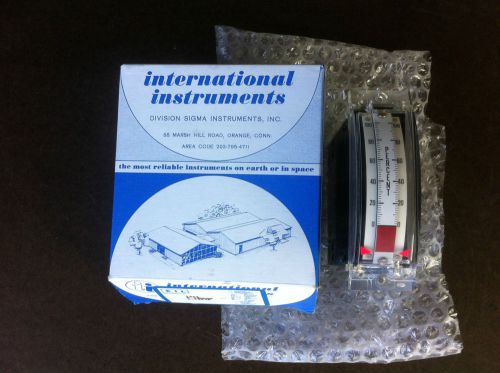
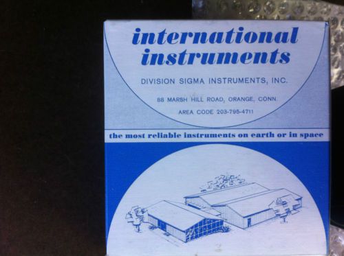
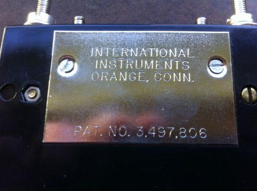
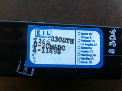
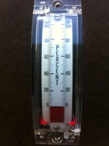
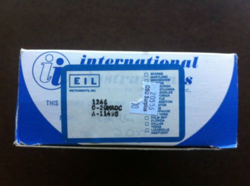
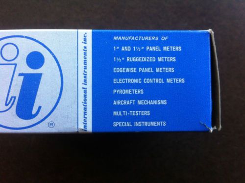
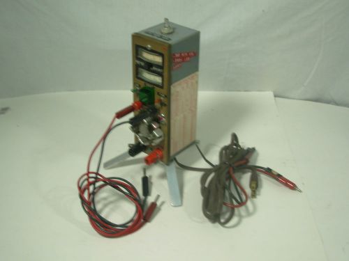
Brand | International Instruments |
| Country of Manufacture | United States | ||
| MPN | 8308TH 1246 0-20MADC A-11498 |
Directions
Similar products from Voltage Testers, Multimeters, Amp & Voltmeters
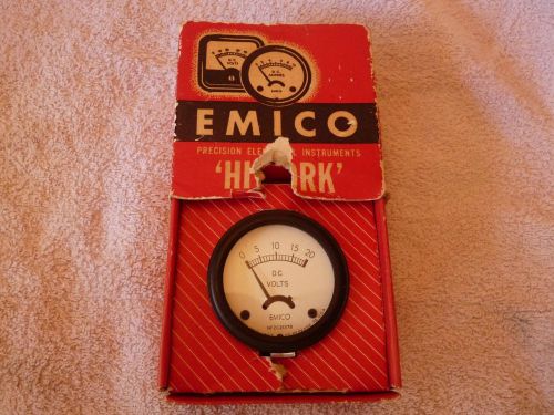
Vintage Emico "High Tork" DC Volt Meter with Original Box
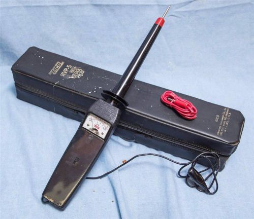
Eico HVP-5 High Voltage Probe 30 Kilovolt Meter
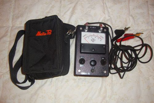
MODEL MT -8455 VOLT-OHMETER AND CARRYING CASE CLOTH.1991 Ameritech tel co.
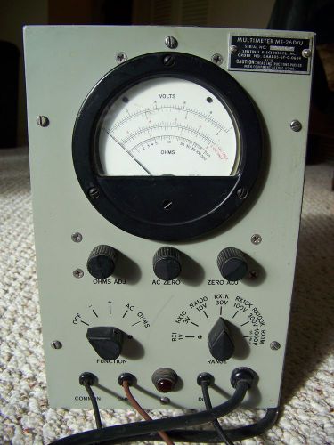
Sentinel Electronics ME-26D/U Vacuum Tube Volt Meter VTVM US Military
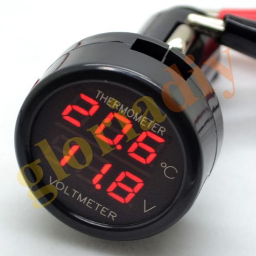
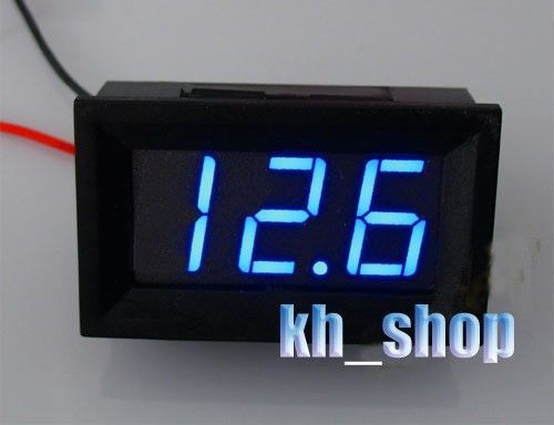
12V/24VDual display dual function car voltage+thermometer display 2 in 1 Red+Red
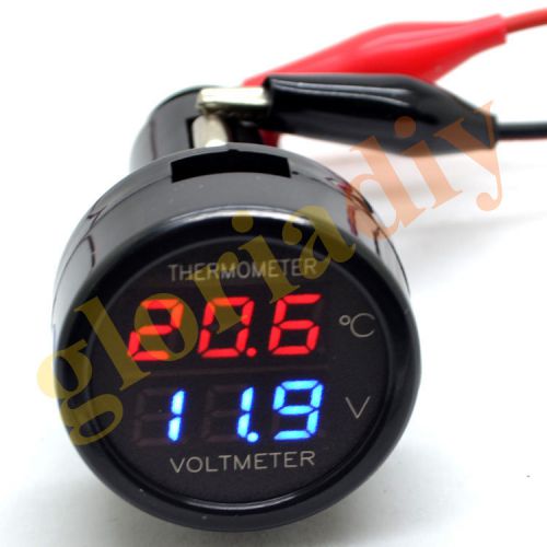
12V/24VDual display dual function car voltage+thermometer display 2 in1 Red+Blue
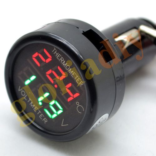
12V/24VDual display dual function car voltage+thermometer display 2in1 Red+Green
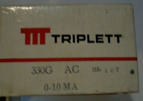
Triplett 330G AC Meter Movement 0 -5 AC Amperes NOS NIB 330 G
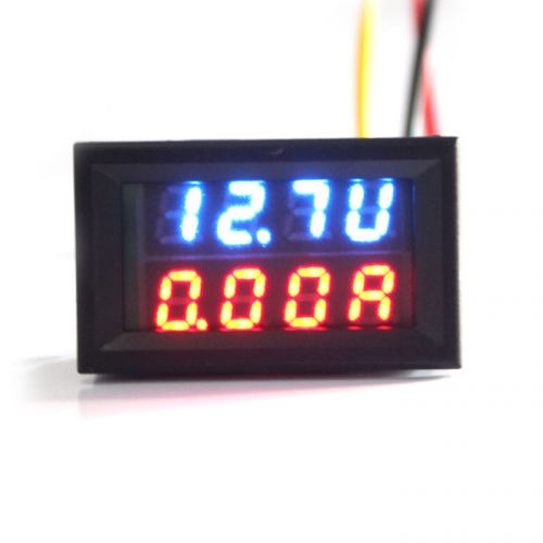
Dual LED DC Digital Ammeter Voltmeter LCD Panel Amp Volt Meter 5A 30V Special
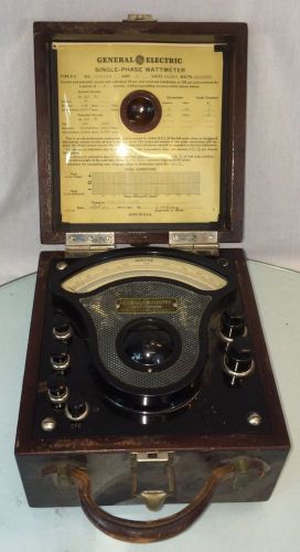
ANTIQUE GENERAL ELECTRIC P-3 POLYPHASE WATTMETER
US LED Digital Volt Meter DC 4.5~30V For 9V 12V 24V No Power Needed Panel
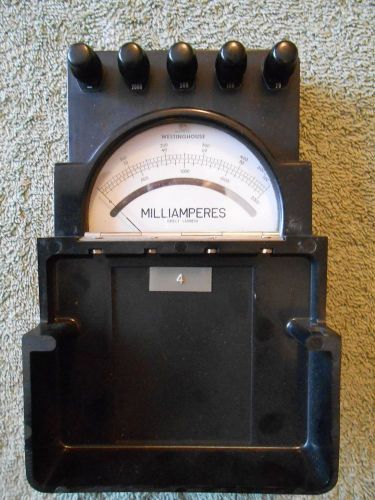
Vtg. Westinghouse DC Milliamperes Meter 0-2000mA Scale - Type PIX-14
Mystery gauge, Volts-Milliamperes W.H. Brady or homemade?
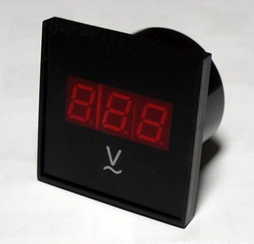
LED Digital Tube Display AC voltage meter for AVR generator( from AC80-300V)
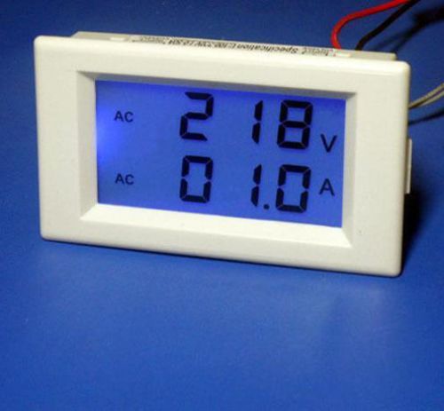
Digital AC100-300V 0-50A LCD DUAL DISPLAY PANEL Combo VOLT/AMP meter
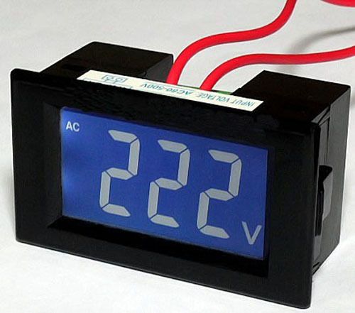
AC80-500V Digital LCD Panel Meter AC Voltage Meter LCD Voltage
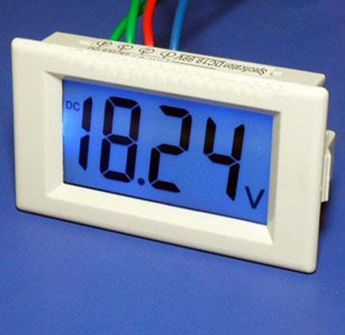
Digital LCD DC VOLTAGE METER (MEASUREMENT RANGE FROM DC 0-600V)
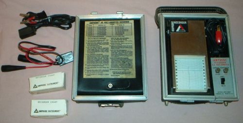
AMPROBE - RECORDING METER - AC VOLT / AMMETER - AVA83 w/ Probes, 2 Rolls Charts
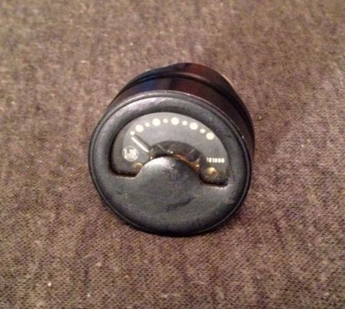
Panel Meter DeJur Amsco Spec SDC 101000 Milliampers Scale Gauge
People who viewed this item also vieved
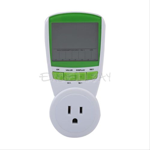
230V energy meter, Watt Voltage Volt Meter LCD Monitor Analyzer W/ power factor
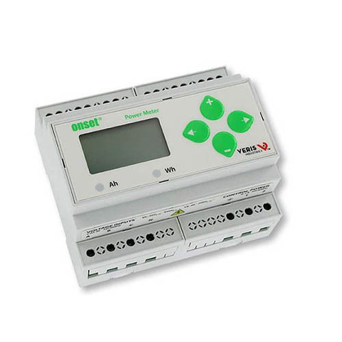
Onset T-VER-E50B2, Power & Energy Meter
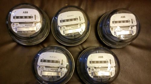
ABB Elster Kilowatt hour Power Meter LOT of 5
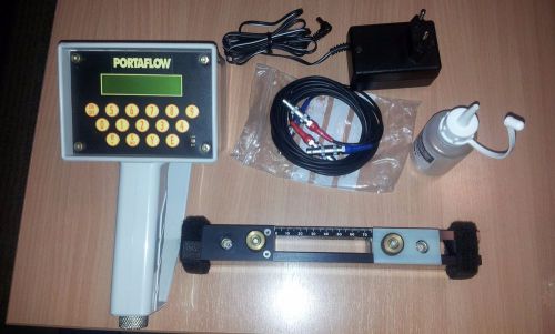
Ultrasonic Flowmeter clamp on sensor (DN13mm-115mm)
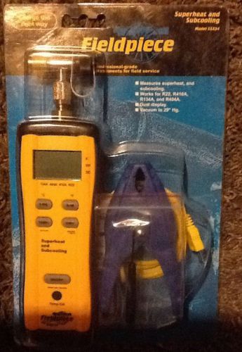
Fieldpiece SSX34 Superheat and Subcooling Meter
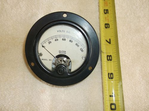
Vintage Collectible Weston Gauge Model 301 KS-7204 Volts D.C.
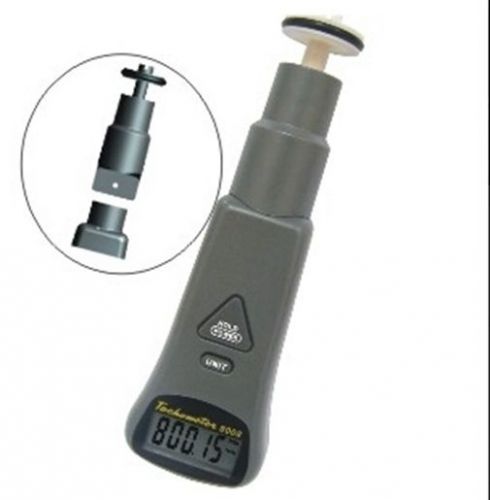
Handheld Contact & Non-Contact 2in1 Combo Tachometer 10-99999 RPM 3-30000 Ft/Min
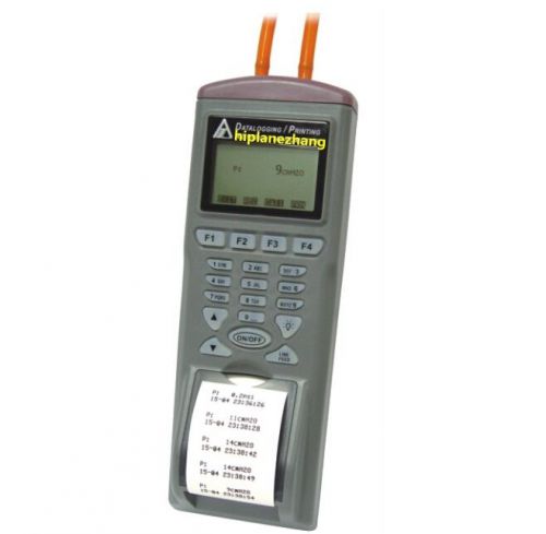
Differential Pressure Meter Gauge Manometer 5PSI Data Log Built-in Printer RS232
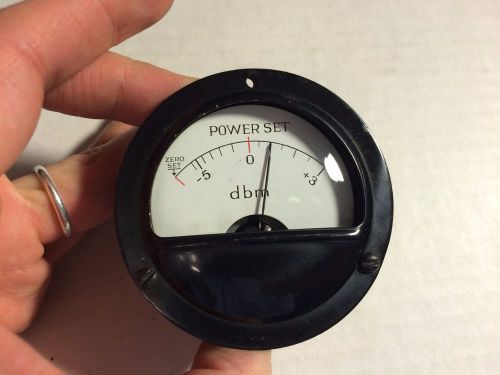
Beautiful Vintage Power Set DBM Meter sealed gauge domed glass needle sticks
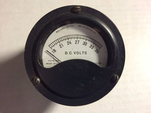
Vintage Roller-Smith DC Volts Meter Type DDH Sealed Gauge Measures 18-36
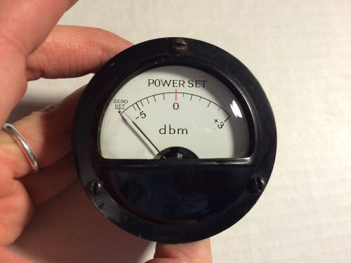
Beautiful Vintage Power Set DBM Meter sealed gauge domed glass
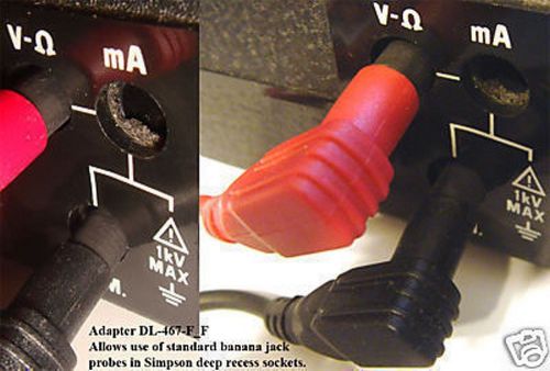
Adapter Set Simpson deep socket meters to Banana Probes
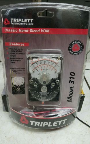
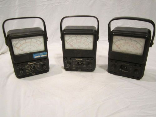
Triplett 310 Classic Hand Sized VOM Free Shipping
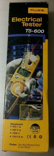
FLUKE T5 600 ELECTRICAL TESTER 600 VOLTS 100 AMPs
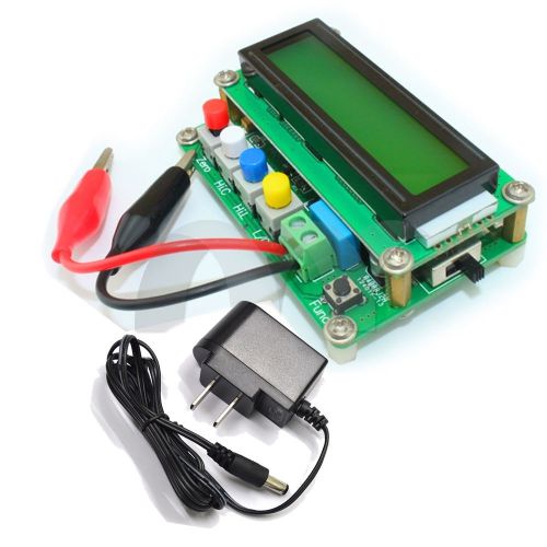
High Precision Inductance/Capacitance L/C Meter LC100-A New
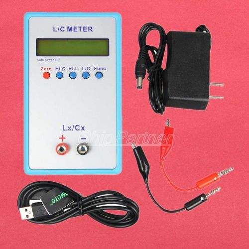
L/C Inductance Capacitance Multimeter Meter LC200A Tool + tracking number
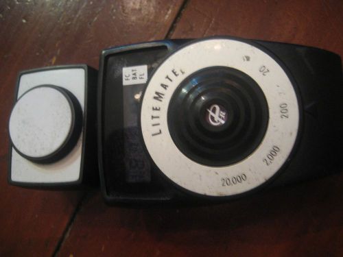
LiteMate FC BAT Photometer Model 501 Vintage
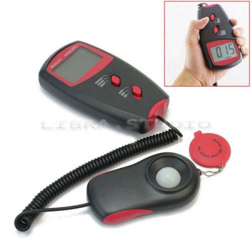
Black Digital Light Meter LX-1010B Luxmeter Meters Luminometer Photometer
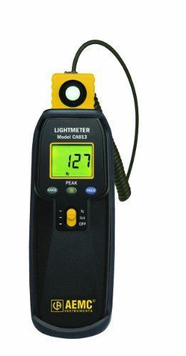
AEMC CA813 PEAK Function Lightmeter, 200,000 lux Range, 0.01 lux Resolution,
By clicking "Accept All Cookies", you agree to the storing of cookies on your device to enhance site navigation, analyze site usage, and assist in our marketing efforts.
Accept All Cookies