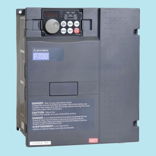
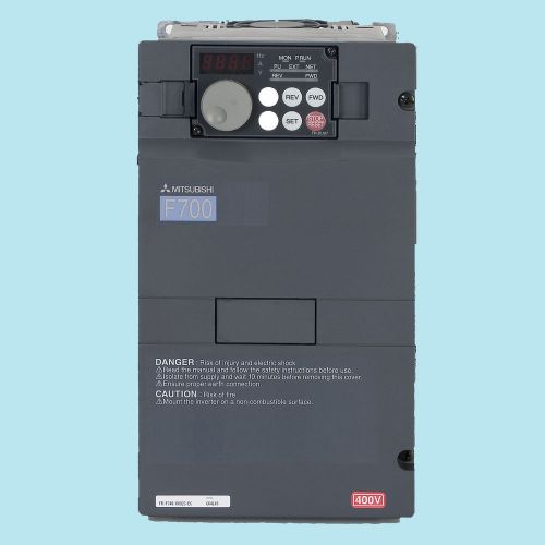
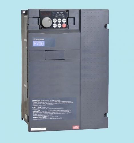
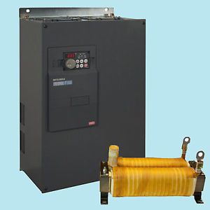
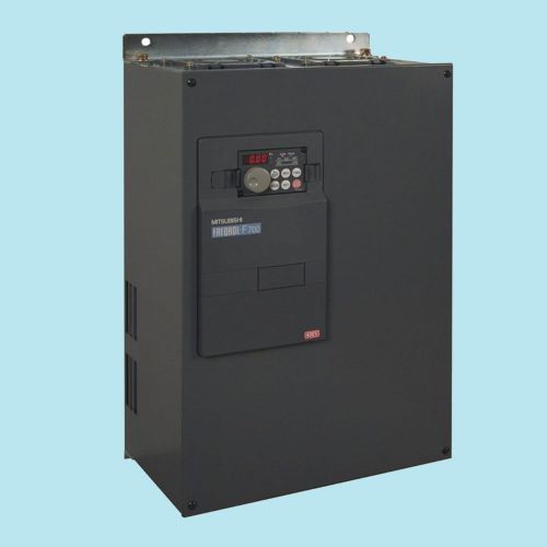
The truly fantastic specifications of the F700, make this VFD from Mitsubishi Electric an absolute must for your drive systems. NEMA 1 UL Type 1 Enclosure Designs: Drive can be mounted as a stand-alone unit where required. (Plenum rated) Built-in BACnet MS/TP Built-in PLC; programs using GX Developer Two I/O cards can be installed simultaneously Remote I/O capability: All the drive I/O can be read or controlled over a network Optional FR-PU07-01 keypad can be mounted remotely, display HAND/AUTO, and display the value of three monitors Energy Savings: Optimum Excitation Control 3 user programmable skip frequencies Windmill start: Catch a reverse spinning load Pre-charge mode PID sleep mode Second PID function Regeneration avoidance Built-in EMC filter: Conforms to EN61800-3 2nd environmental UL Listed for single phase input F700 Ratings 200-240V Class Input: 1 Phase/3 Phase - Output Voltage: 3 Phase 200-240V at 60Hz Voltage Tolerance: 170-264V at 60Hz Available Braking Torque: 15% Torque Continuous SLD (40°C) LD Model Number (*4) Frame Size Cooling Method Protective Rating Stocked Item 110% OL / 1min 120% OL / 1min 120% OL / 3 sec 150% OL / 3 sec Hp (*1) FLA Hp (*1) FLA 1 4.6 1 4.2 FR-F720-00046-NA A Self Cooling UL Type 1 - Plenum Rated S 2 7.7 2 7 FR-F720-00077-NA B S 3 10.5 3 9.6 FR-F720-00105-NA C Forced Air Cooled S 5 16.7 5 15.2 FR-F720-00167-NA C S 7.5 25 7.5 23 FR-F720-00250-NA C S 10 34 10 31 FR-F720-00340-NA D S 15 49 15 45 FR-F720-00490-NA D S 20 63 20 58 FR-F720-00630-NA E S 25 77 25 70 FR-F720-00770-NA F S 30 93 30 85 FR-F720-00930-NA F S 40 125 40 114 FR-F720-01250-NA F IP00 (*2) S 50/60 154 50 140 FR-F720-01540-NA G S 60 187 60 170 FR-F720-01870-NA H S 75 233 75 212 FR-F720-02330-NA H S 40 125 40 114 FR-F720-01250-NAN1 F NEMA 1 - 50/60 154 50 140 FR-F720-01540-NAN1 G - 60 187 60 170 FR-F720-01870-NAN1 H - 75 233 75 212 FR-F720-02330-NAN1 H - 100/125 316 100 288 FR-F720-03160-NA K IP00 (*2) S 150 380 125 346 FR-F720-03800-NA K S 200 475 150 432 FR-F720-04750-NA K - Notes: See below. F700 Ratings 480V Class Input: 1 Phase / 3 Phase • Output Voltage: 3 Phase 380-480V at 50/60Hz Voltage Tolerance: 323-528V at 50/60Hz • Available Braking Torque: 15% Torque Continuous SLD (40°C) LD Model Number (*4) Frame Size Cooling Method Protective Rating Stocked Item 110% OL / 1min 120% OL / 1min 120% OL / 3 sec 150% OL / 3 sec Hp (*1) FLA Hp (*1) FLA 1 2.3 1 2.1 FR-F740-00023-NA C Self Cooling UL Type 1 - Plenum rated S 2 3.8 2 3.5 FR-F740-00038-NA C S 3 5.2 3 4.8 FR-F740-00052-NA C S 5 8.3 5 7.6 FR-F740-00083-NA C S 7.5 12.6 7.5 11.5 FR-F740-00126-NA C S 10 17 10 16 FR-F740-00170-NA D Forced Air Cooled S 15 25 15 23 FR-F740-00250-NA D S 20 31 20 29 FR-F740-00310-NA E S 25 38 25 35 FR-F740-00380-NA E S 30 47 30 43 FR-F740-00470-NA F S 40 62 40 57 FR-F740-00620-NA F S 50/60 77 50 70 FR-F740-00770-NA G IP00 (*3) S 60 93 60 85 FR-F740-00930-NA H S 75 116 75 106 FR-F740-01160-NA H S 50/60 77 50 70 FR-F740-00770-NAN1 G NEMA 1 - 60 93 60 85 FR-F740-00930-NAN1 H - 75 116 75 106 FR-F740-01160-NAN1 H - Notes: See below. Input: 1 Phase / 3 Phase • Output Voltage: 3 Phase 380-480V at 50/60Hz • Voltage Tolerance: 323-550V at 50/60Hz Available Braking Torque: 15% Torque Continuous • DC Link Choke is Included With The VFD SLD (40°C) LD Model Number (*4) Frame Size Fan Protective Rating Stocked Item 110% OL / 1min 120% OL / 1min 120% OL / 3 sec 150% OL / 3 sec Hp (*1) FLA Hp (*1) FLA 100/150 180 100 144 FR-F740-01800-NA H Forced Air Cooled IP00 (*2) S 150 216 150 180 FR-F740-02160-NA J S 200 260 150 216 FR-F740-02600-NA J S 250 325 200 260 FR-F740-03250-NA K S 300 361 250 325 FR-F740-03610-NA K S 350 432 300 361 FR-F740-04320-NA L S 400 481 350 432 FR-F740-04810-NA L S 450 547 400 481 FR-F740-05470-NA M S 500 610 450 547 FR-F740-06100-NA M S 550 683 500 610 FR-F740-06830-NA M S 650 770 550 683 FR-F740-07700-NA N IP000 (*3) S 700 866 650 770 FR-F740-08660-NA N S 800 962 700 866 FR-F740-09620-NA P S 900 1094 800 962 FR-F740-10940-NA P - 1000 1212 900 1094 FR-F740-12120-NA P - Notes: 1. Motor ratings shown are intended as guidelines only - based on 4 pole standard induction motors. 2. NEMA 1 conduit adapter option required for types 01250 - 04750 200V class product. 3. NEMA 1 conduit adapter option required for types 00770 - 06830 400V class product. 4. For single phase input, derate output current by 40% (Models up to F720-03800-NA, F740-04810-NA.) F700 General Specifications Control Specifications Control System High carrier frequency PWM control (V/F control)/optimum excitation control/simple magnetic flux vector control Output Frequency Range 0.5 to 400Hz Frequency Setting Resolution Analog Input 0.015Hz/0 to 60Hz (terminal 2, 4: 0 to 10V/12bit); 0.03Hz/0 to 60Hz (terminal 2, 4: 0 to 5V/11bit, 0 to 20mA/approx. 11bit, terminal 1: -10V to +10V/11bit); 0.06Hz/0 to 60Hz (terminal 1: 0 to ±5V/10bit) Digital Input 0.01Hz Frequency Accuracy Analog Input Within ±0.2% of the max. output frequency (25°C ± 10°C) Digital Input Within 0.01% of the set output frequency Voltage/Frequency Characteristics Base frequency can be set from 0 to 400Hz. Constant torque/variable torque pattern or adjustable 5 points V/F can be selected Starting Torque 120% (3Hz) when set to simple magnetic flux vector control and slip compensation Acceleration/Deceleration Time Setting 0 to 3600s (acceleration and deceleration can be set individually), linear or S-pattern acceleration/deceleration mode can be selected. DC Injection Brake Operation frequency (0 to 120Hz), operation time (0 to 10s), operation voltage (0 to 30%) variable Stall Prevention Operation Level Operation current level can be set (0 to 150% adjustable), whether to use the function or not can be selected Operation Specifications Frequency Setting Signal Analog Input Terminal 2, 4: 0 to 10V, 0 to 5V, 4 to 20mA can be selected. Terminal 1: -10 to +10V, -5 to 5V can be selected. Digital Input Four-digit BCD or 16-bit binary using the setting dial of the operation panel (when used with the option FR-A7AX) Start Signal Available individually for forward and reverse rotation. Start signal automatic self-holding input (3-wire input) can be selected. Input Signals Select any twelve signals using Pr.178 to Pr.189 (input terminal function selection) from among multi-speed selection, second function selection, terminal 4 input selection, JOG operation selection, selection of automatic restart after instantaneous power failure, external thermal relay input, HC connection (inverter operation enable signal), HC connection (instantaneous power failure detection), PU operation/external interlock signal , PID control enable terminal, PU operation, external operation switchover, output stop, start self-holding selection, forward rotation command, reverse rotation command, inverter reset, PTC thermistor input, PID forward reverse operation switchover, PU-NET operation switchover, NET-external operation switchover, command source switchover. Operational Functions Max. and min. frequency settings, frequency jump operation, external thermal relay input selection, polarity reversible operation, automatic restart after instantaneous power failure operation, continuous operation at an instantaneous power failure, commercial power supply, inverter switchover operation, forward/reverse rotation prevention, operation mode selection, PID control, computer link operation (RS-485). Output Signals Operating Status Select any seven signals using Pr.190 to Pr.196 (output terminal function selection) from among inverter running, up-to-speed, instantaneous power failure/undervoltage, overload warning, output frequency detection, second output frequency detection, electronic thermal relay function pre-alarm, PU operation mode, inverter operation ready, output current detection, zero current detection, PID lower limit, PID upper limit, PID forward rotation reverse rotation output, commercial power supply-inverter switchover MC1, commercial power supply-inverter switchover MC2, commercial power supply-inverter switchover MC3, fan fault output, heatsink overheat pre-alarm, inverter running start command on, deceleration at an instantaneous power failure, PID control activated, during retry, during PID output suspension, life alarm, input MC stop signal, power savings average value update timing, current average monitor, alarm output 2, maintenance timer alarm, remote output, minor failure output, alarm output. Open collector output (5 points), relay output (2 points) and alarm code of the inverter can be output (4 bit) from the open collector. When Used With The FR-A7AY (Option) Select any seven signals using Pr. 313 to Pr. 319 (extension output terminal function selection) from among control circuit capacitor life, main circuit capacitor life, cooling fan life, inrush current limit circuit life. Analog Output Select from output frequency, motor current (steady or peak value), output voltage, frequency setting value, running speed, converter output voltage (steady or peak value), electronic thermal relay function load factor, input power, output power, load meter, reference voltage output, motor load factor, energy saving effect, PID set value, PID process value using Pr. 54 “CA terminal function selection (analog current output)” and Pr. 158 “AM terminal function selection (analog output)”. Display Parameter Unit (FR-DU07/FR-PU04) Operating Status Output frequency, motor current (steady or peak value), output voltage, alarm indication, frequency setting, running speed, converter output voltage (steady or peak value), electronic thermal load factor, input voltage, output voltage, road meter, cumulative energization time, actual operation time, motor load factor, cumulative energization power, power saving effect, cumulative saving power, PID set point, PID process value, PID deviation value, inverter I/O terminal monitor, input terminal option monitor (*1), output terminal option monitor (*1), option fitting status monitor (*2), terminal assignment status (*2) Alarm Definition Alarm definition is displayed when the protective function is activated, the output voltage/current/frequency/cumulative energization time right before the protection function was activated and the past 8 alarm definitions are stored. Interactive Guidance Operation guide/troubleshooting with a help function. (*2) Protective/Warning Function Overcurrent during acceleration, overcurrent during constant speed, overcurrent during deceleration, overvoltage during acceleration, overvoltage during constant speed, overvoltage during deceleration, inverter protection thermal operation, heatsink overheat, instantaneous power failure occurrence, undervoltage, input phase failure, motor overload, output side earth (ground) fault overcurrent, output phase failure, external thermal relay operation, PTC thermistor operation, option alarm, parameter error, PU disconnection, retry count excess, CPU alarm, power supply short for operation panel, 24VDC power output short, output current detection value over, inrush resistance overheat, communication alarm (inverter), analog input alarm, internal circuit alarm (15V power supply), fan fault, overcurrent stall prevention, overvoltage stall prevention, electronic thermal prealarm, PU stop, maintenance timer alarm (*1), parameter write error, copy operation error, operation panel lock. Environment Ambient Temperature -10°C to +50°C (non-freezing) Ambient Humidity 90% RH or less (non-condensing) Storage Temperature (*3) -20°C to +65°C Atmosphere Indoors (without corrosive gas, flammable gas, oil mist, dust and dirt, etc.) Altitude, Vibration Maximum 1000m above sea level, 5.9m/s2 or less (conforms to JIS C 0040) F700 Series Terminal Connection Diagram F700 Control Terminal Layout
By clicking "Accept All Cookies", you agree to the storing of cookies on your device to enhance site navigation, analyze site usage, and assist in our marketing efforts.