US $380
Directions
Similar products from Development Boards & Programmers
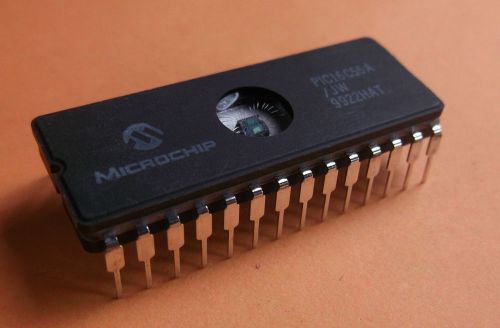
PIC16C55A Microcontroller 28 pin DIP ***QTY=2*** manf. by Microchip
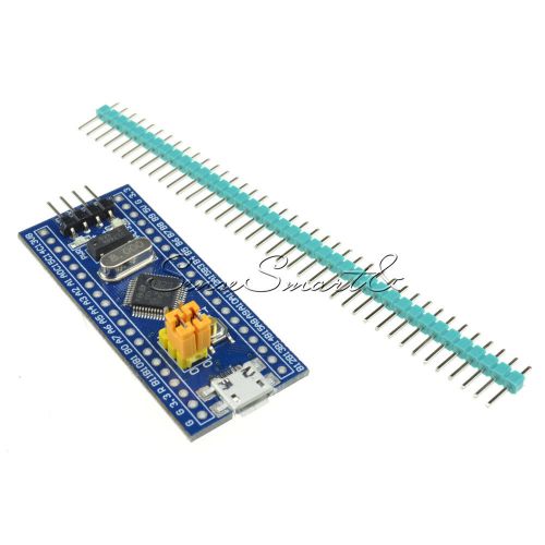
STM32F103C8T6 ARM STM32 Minimum System Development Board Module For Arduino ST
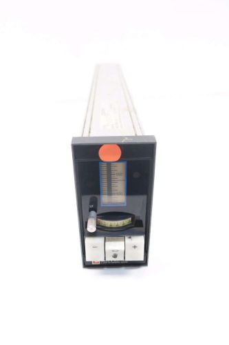
LEEDS NORTHRUP 440-1-20-33-65-A999 CENTRY 4-20V-DC 0.3A AMP CONTROLLER D532476
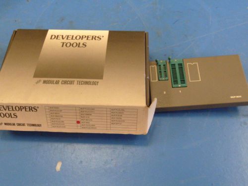
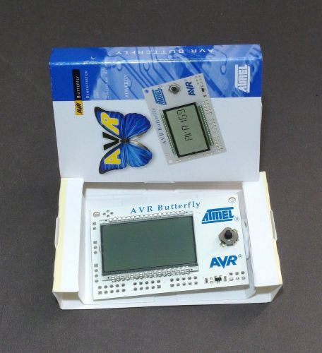
Modular Circuit Developers' Tools MUP-MAX 000004
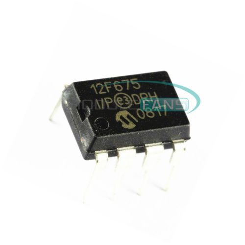
10PCS PIC12F675 12F675 PIC12F675-I/P DIP-8 Microcontroller CHIP IC
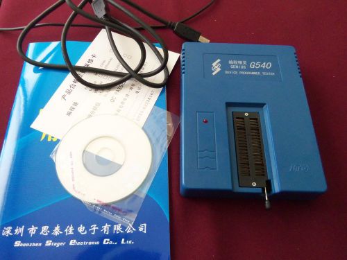
Genius G540 USB universal Bios EPROM CHIP Programmer
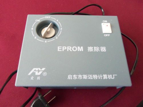
Ultraviolet Light UV EPROM Eraser
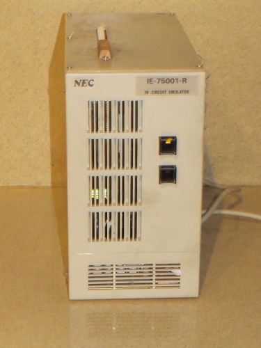
NEC IE-75001-R IN CIRCUIT EMULATOR
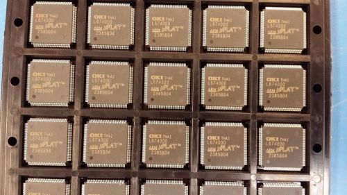
(1PC) ML674000TB OKI 32-BIT, 33.333MHz, RISC MICROCONTROLLER, PQFP128
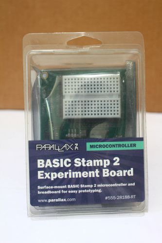
BASIC Stamp 2 Experiment Board by Parallax
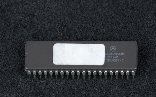
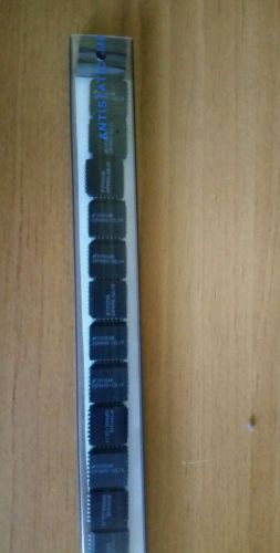
Motorola XC/MC68HC705C5S MC68HC705C8S MCU 8-Bit HC05 CPU 4K EPROM DIP-40
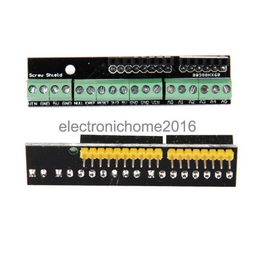
Screw Shield Screwshield Assembled Terminal Expansion Board for Arduino
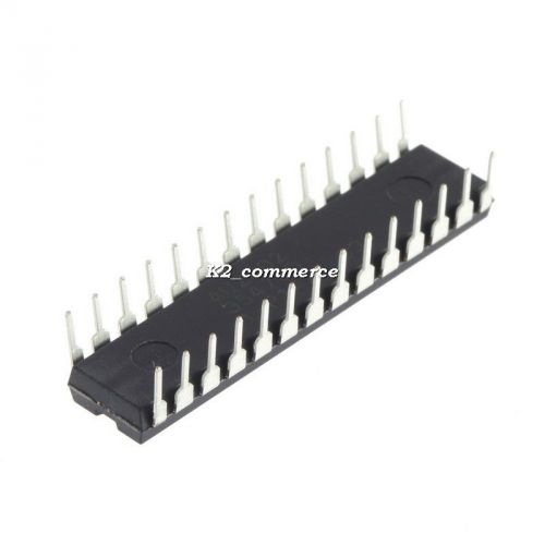
NEW 1PC 8-Bit Micro Controller Microcontroller ATmega328P-PU K2
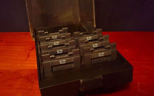
DATA I/O 3900/3980 PLCC Programming Adapters
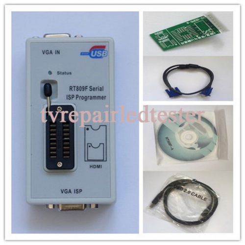
VGA LCD USB Programmer RT809F Serial ISP Programmer PC Repair Tools
Nat.Semiconduct.microcontroller COP840C
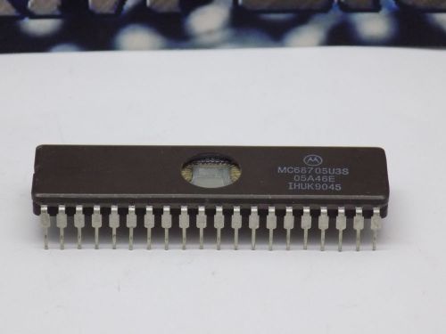
1x Motorola MC68705U3S 8-BIT, Otprom, 2.1 MHz, Microcontroller, CDIP40
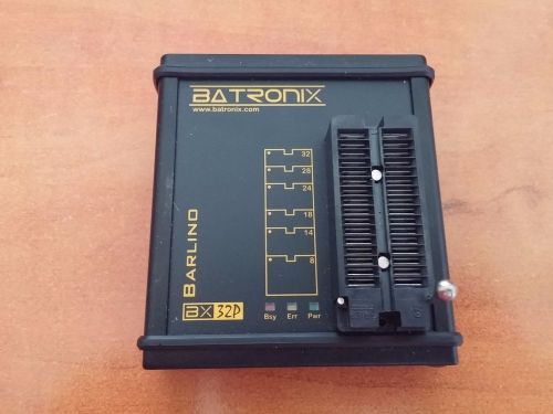
Batronix BX32P Barlino programmer USB
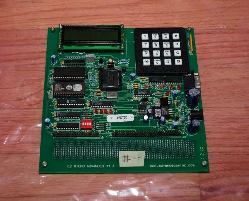
EZ MICRO ADVANCED 11A Tutor Microprocessor Design Course #4
People who viewed this item also vieved
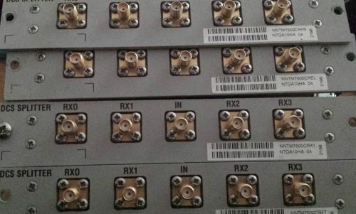
Lot of 4 Nortel NTQA10HA DCS Splitter (b3)
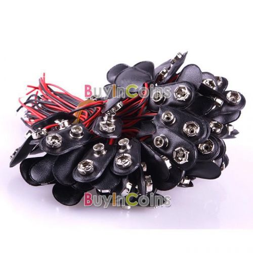
10x 9V Battery Holder Clip Snap Connector Soft Lead Shell I Type 6CM Line
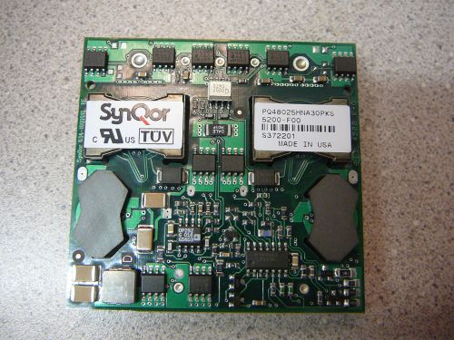
SYNQOR PQ48025HNA30PKS DC/DC Converter 48V In 3.3V Out 30A 1/2 Brick *NEW*
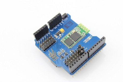
Bluetooth Shield Support Master/Slave Role Mode for Arduino
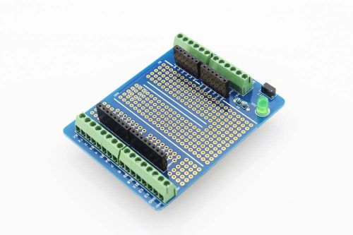
Proto Screw Shield Assembled for Arduino
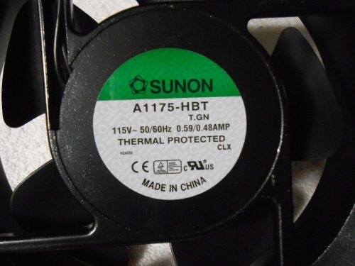
SUNON A1175-HBT - 115V-50/60HZ / 0.59/0.48AMP / 6-3/4" DIA. X 2" WIDE NEW
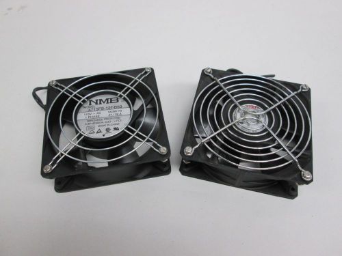
LOT 2 NMB ASSORTED 4715FS-12T-B50 125XR ETRI COOLING FAN D307468
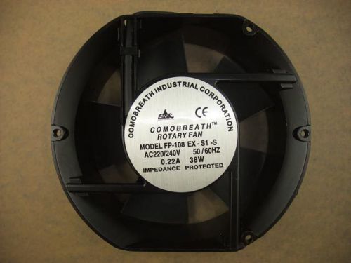
SANXIE FP-108 EX-S1-S 17252 172 x152 x52mm AC220V 856
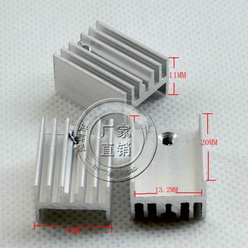
5 pcs - Aluminum Heat Sinks for MOFETs 20mm x 15mm x 10mm - Fast Shipping!
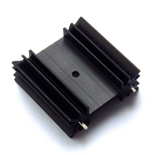
4x TO-220 Heatsink, Small Power Aluminum Heat-Sink
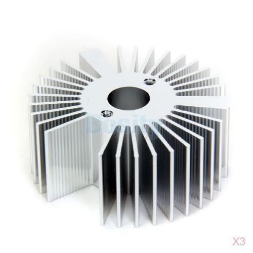
3x Aluminum Heatsink for 3W High Power LED Light Bulb D 2.1" x H 0.9"
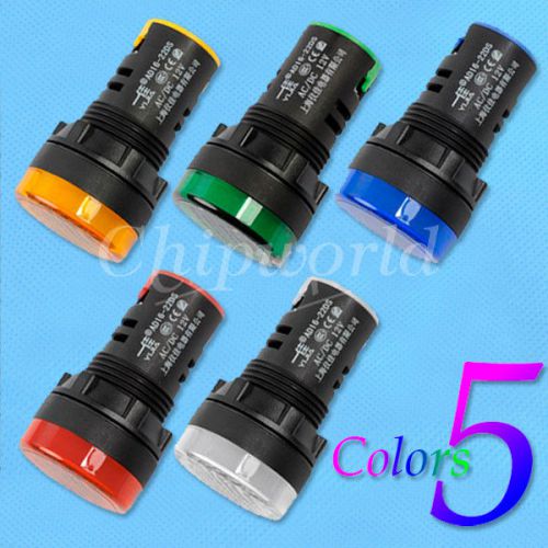
5 Colors Green+Red+Blue+White+Yellow LED Indicator Pilot Signal Light Lamp 12V
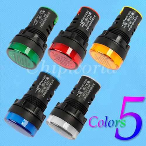
5 Colors Green+Red+Yellow+Blue+White LED Indicator Pilot Signal Light Lamp 24V
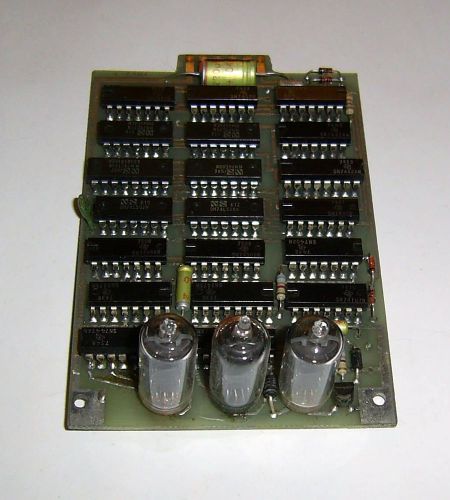
3 DIGIT VINTAGE SPEED RADAR NUMITRON TUBES DISPLAY PCB ASSEMBLY
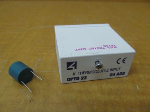
New OPTO 22 K Thermocouple Input G4AD8 G4 AD8
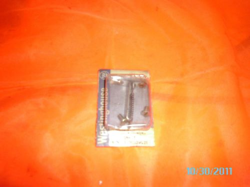
WESTINGHOUSE TYPE A HEATER CAT# FH21 1026
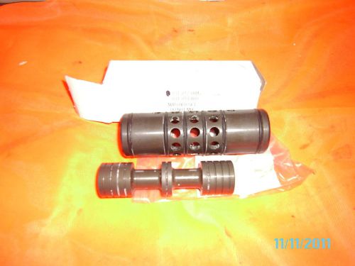
WARREN RUPP SLEEVE & SPOOL SET #031-012-000 1025
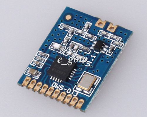
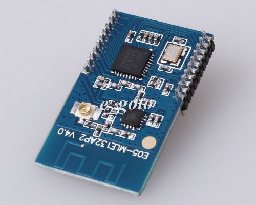
E10-SMD 433MHz SI4463 Wireless Transmission Module 433M 100mW Precise
2.4G nRF24LE1+PA+LNA MCU+nRF24L01 Double Antenna Active RFID Precise
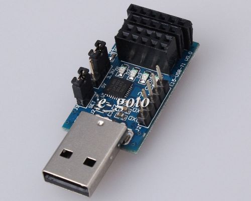
Wireless Serial Port Module USB to TTL Pinboard for Wireless Module Precise
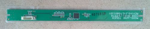
SAMSUNG LA55A610 TOUCH FUNCTION KEY BOARD BN96-08121B A07503B BN41-00997A
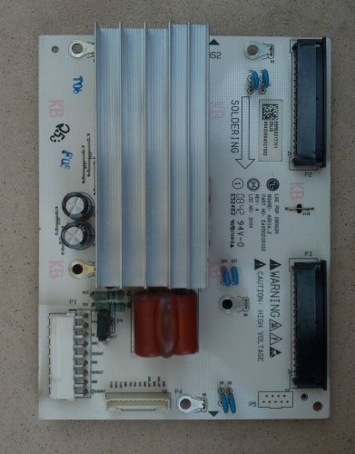
LG 42PG60UD X-MAIN BOARD EBR50217701
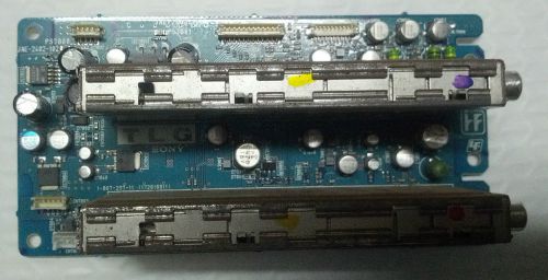
SONY KLV-V40A20 TLG BOARD 1-867-297-11 A-1118-396-A
By clicking "Accept All Cookies", you agree to the storing of cookies on your device to enhance site navigation, analyze site usage, and assist in our marketing efforts.
Accept All Cookies