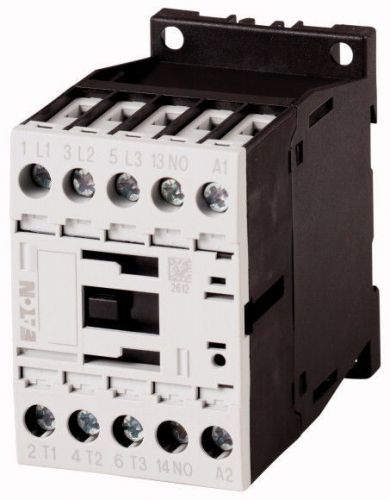
Rated operational current AC-3 380 V 400 V Ie A 15.5 AC-1 Conventional free air thermal current, 3 pole, 50 - 60 Hz Open at 40 °C Ith =Ie A 22 enclosed Ith A 18 Conventional free air thermal current, 1 pole open Ith A 50 enclosed Ith A 45 Max. rating for three-phase motors, 50 - 60 Hz AC-3 220 V 230 V P kW 4 380 V 400 V P kW 7.5 660 V 690 V P kW 7 AC-4 220 V 230 V P kW 2 380 V 400 V P kW 3 660 V 690 V P kW 4.4 Contacts N/O = Normally open 1 N/O Contact sequence 210S026 Instructions Contacts to EN 50 012. Can be combined with auxiliary contact DILM32-XHI.. DILA-XHI(V).. Voltage AC/DC AC operation Technical data General Standards IEC/EN 60947, VDE 0660, UL, CSA Lifespan, mechanical AC operated Operations x 106 10 DC operated Operations x 106 10 Operating frequency, mechanical AC operated Operations/h 5000 DC operated Operations/h 5000 Climatic proofing Damp heat, constant, to IEC 60068-2-78 Damp heat, cyclic, to IEC 60068-2-30 Ambient temperature °C Open °C -25 - +60 Enclosed °C - 25 - 40 Storage °C - 40 - 80 Mounting position 210N017 Mechanical shock resistance (IEC/EN 60068-2-27) Half-sinusoidal shock, 10 ms Main contacts N/O contact g 10 Auxiliary contacts N/O contact g 7 N/C contact g 5 Mechanical shock resistance (IEC/EN 60068-2-27) when tabletop-mounted Half-sinusoidal shock, 10 ms Main contacts N/O contact g 5.7 Auxiliary contacts N/O contact g 3.4 N/C contact g 3.4 Degree of Protection IP20 Protection against direct contact when actuated from front (EN 50274) Finger and back-of-hand proof Weight AC operated kg 0.23 DC operated kg 0.28 Terminal capacity main cable Solid mm2 1 x (0.75 - 4) 2 x (0.75 - 2.5) Flexible with ferrule mm2 1 x (0.75 - 2.5) 2 x (0.75 - 2,5) Also without ferrule. Solid or stranded AWG 18 - 10 Main cable connection screw/bolt M3.5 Tightening torque Nm 1.2 Terminal capacity control circuit cables Solid mm2 1 x (0.75 - 4) 2 x (0.75 - 2.5) Flexible with ferrule mm2 1 x (0.75 - 2.5) 2 x (0.75 - 2.5) Solid or stranded AWG 18 - 14 Control circuit cable connection screw/bolt M3.5 Tightening torque Nm 1.2 Tool Main cable Pozidriv screwdriver Size 2 Standard screwdriver mm 0.8 x 5.5 1 x 6 Control circuit cables Pozidriv screwdriver Size 2 Standard screwdriver mm 0.8 x 5.5 1 x 6 Main conducting paths Rated impulse withstand voltage Uimp V AC 8000 Overvoltage category/pollution degree III/3 Rated insulation voltage Ui V AC 690 Rated operational voltage Ue V AC 690 Safe isolation to EN 61140 between coil and contacts V AC 400 between the contacts V AC 400 Making capacity (p.f. to IEC/EN 60947) Up to 690 V A 155 Breaking capacity 220 V 230 V A 124 380 V 400 V A 124 500 V A 100 660 V 690 V A 70 Short-circuit rating Short-circuit protection maximum fuse Type “2” coordination 400 V gG/gL 500 V A 20 690 V gG/gL 690 V A 20 Type “1” coordination 400 V gG/gL 500 V A 63 690 V gG/gL 690 V A 50 AC AC-1 Rated operational current Conventional free air thermal current, 3 pole, 50 - 60 Hz Open at 40 °C Ith =Ie A 22 at 50 °C Ith =Ie A 21 at 55 °C Ith =Ie A 21 at 60 °C Ith =Ie A 20 enclosed Ith A 18 Conventional free air thermal current, 1 pole open Ith A 50 enclosed Ith A 45 AC-3 Rated operational current Open, 3-pole: 50 – 60 Hz 220 V 230 V Ie A 15.5 240 V Ie A 15.5 380 V 400 V Ie A 15.5 415 V Ie A 15.5 440V Ie A 15.5 500 V Ie A 12.5 660 V 690 V Ie A 9 380 V 400 V Ie A 15.5 Motor rating P kWh 220 V 230 V P kW 4 240V P kW 4.6 380 V 400 V P kW 7.5 415 V P kW 8 440 V P kW 8.4 500 V P kW 7.5 660 V 690 V P kW 7 AC-4 Open, 3-pole: 50 – 60 Hz 220 V 230 V Ie A 7 240 V Ie A 7 380 V 400 V Ie A 7 415 V Ie A 7 440 V Ie A 7 500 V Ie A 6 660 V 690 V Ie A 5 Motor rating P kWh 220 V 230 V P kW 2 240 V P kW 2.2 380 V 400 V P kW 3 415 V P kW 3.4 440 V P kW 3.6 500 V P kW 3.5 660 V 690 V P kW 4.4 DC Rated operational current, open DC-1 60 V Ie A 20 110 V Ie A 20 220 V Ie A 15 440 V Ie A 1.3 DC-3 60 V Ie A 20 110 V Ie A 20 220 V Ie A 1.5 440 V Ie A 0.2 DC-5 60 V Ie A 20 110 V Ie A 20 220 V Ie A 1.5 440 V Ie A 0.2 Current heat loss 3-pole at Ith W 2.7 Current heat loss at Ie to AC-3/400 V W 1.5 Impedance per pole m? 2.5 Magnet systems Voltage tolerance x Uc AC operated Pick-up x Uc 0.8 - 1.1 Drop-out voltage AC operated Drop-out x Uc 0.3 - 0.6 DC operated Pick-up x Uc 0.7 - 1.2 DC operated Drop-out x Uc 0.15 - 0.6 Notes at least smoothed two-phase bridge rectifier or three-phase rectifier Power consumption of the coil in a cold state and 1.0 x Uc 50 Hz Pick-up VA 24 50 Hz Sealing VA 3.4 50 Hz Sealing W 1.2 60 Hz Pick-up VA 30 60 Hz Sealing VA 4.4 60 Hz Sealing W 1.4 50/60 Hz Pick-up VA 27 25 50/60 Hz Sealing VA 4.2 3.3 50/60 Hz Sealing W 1.4 1.2 DC operated Pick-up W 4.5 DC operated Sealing W 4.5 Duty factor % DF 100 Switching times at 100 % Uc (approximate values) Main contacts AC operated Closing delay ms 15 - 21 Opening delay ms 9 - 18 DC operated ms Closing delay ms 31 Opening delay ms 12 Arcing time ms 10 Lifespan, mechanical; Coil 50/60 Hz x 106 Mechanical lifespan at 50 Hz approx. 30% lower than under “Technical data, general” Electromagnetic compatibility (EMC) Emitted interference to EN 60947-1 Interference immunity to EN 60947-1 Design verification as per IEC/EN 61439 Technical data for design verification Rated operational current for specified heat dissipation In A 15.5 Heat dissipation per pole, current-dependent Pvid W 0.5 Equipment heat dissipation, current-dependent Pvid W 0 Static heat dissipation, non-current-dependent Pvs W 1.4 Heat dissipation capacity Pdiss W 0 Operating ambient temperature min. °C -25 Operating ambient temperature max. °C 60 IEC/EN 61439 design verification 10.2 Strength of materials and parts 10.2.2 Corrosion resistance Meets the product standard's requirements. 10.2.3.1 Verification of thermal stability of enclosures Meets the product standard's requirements. 10.2.3.2 Verification of resistance of insulating materials to normal heat Meets the product standard's requirements. 10.2.3.3 Verification of resistance of insulating materials to abnormal heat and fire due to internal electric effects Meets the product standard's requirements. 10.2.4 Resistance to ultra-violet (UV) radiation Meets the product standard's requirements. 10.2.5 Lifting Does not apply, since the entire switchgear needs to be evaluated. 10.2.6 Mechanical impact Does not apply, since the entire switchgear needs to be evaluated. 10.2.7 Inscriptions Meets the product standard's requirements. 10.3 Degree of protection of ASSEMBLIES Does not apply, since the entire switchgear needs to be evaluated. 10.4 Clearances and creepage distances Meets the product standard's requirements. 10.5 Protection against electric shock Does not apply, since the entire switchgear needs to be evaluated. 10.6 Incorporation of switching devices and components Does not apply, since the entire switchgear needs to be evaluated. 10.7 Internal electrical circuits and connections Is the panel builder's responsibility. 10.8 Connections for external conductors Is the panel builder's responsibility. 10.9 Insulation properties 10.9.2 Power-frequency electric strength Is the panel builder's responsibility. 10.9.3 Impulse withstand voltage Is the panel builder's responsibility. 10.9.4 Testing of enclosures made of insulating material Is the panel builder's responsibility. 10.10 Temperature rise The panel builder is responsible for the temperature rise calculation. Eaton will provide heat dissipation data for the devices. 10.11 Short-circuit rating Is the panel builder's responsibility. The specifications for the switchgear must be observed. 10.12 Electromagnetic compatibility Is the panel builder's responsibility. The specifications for the switchgear must be observed. 10.13 Mechanical function The device meets the requirements, provided the information in the instruction leaflet (IL) is observed. Technical data ETIM 6.0 Low-voltage industrial components (EG000017) / Power contactor, AC switching (EC000066) Electric engineering, automation, process control engineering / Low-voltage switch technology / Contactor (LV) / Power contactor, AC switching (ecl@ss8.1-27-37-10-03 [AAB718012]) Rated control supply voltage Us at AC 50HZ V 230 - 230 Rated control supply voltage Us at AC 60HZ V 240 - 240 Rated control supply voltage Us at DC V 0 - 0 Voltage type for actuating AC Rated operation current Ie at AC-1, 400 V A 18 Rated operation current Ie at AC-3, 400 V A 15.5 Rated operation power at AC-3, 400 V kW 7.5 Rated operation current Ie at AC-4, 400 V A 7 Rated operation power Ie at AC-4, 400 V kW 3 Modular version No Number of auxiliary contacts as normally open contact 1 Number of auxiliary contacts as normally closed contact 0 Type of electrical connection of main circuit Screw connection Number of normally closed contacts as main contact 0 Number of main contacts as normally open contact 3 Payment We only accept payment through Paypal. Please make sure you have a valid PayPal account prior bidding. Please pay for your item within 5 days of the auction end time. Delivery details All items will be shipped to buyer's ebay address. Before you pay, please make sure your address in ebay matches the address you would like us to ship to.We are not responsible for any wrong or undeliverable addresses. Import duties, taxes and charges are not included in the item price or shipping charges. These charges are the buyer's responsibility. Please check with your country's customs before making you purchase. Items will be shipped within 1 business day on payment received. About us Our goal is to make sure you are a happy buyer and pleasant shopping with us. Please email us before leaving any 1 or 2 ratings, negative feedback or open any ebay or paypal dispute. We understand the concerns and frustrations you might have, and will do our endeavor to resolve the issues. Please give us the opportunity to resolve any problem.
By clicking "Accept All Cookies", you agree to the storing of cookies on your device to enhance site navigation, analyze site usage, and assist in our marketing efforts.