

US $270
| Condition: |
New: A brand-new, unused, unopened, undamaged item in its original packaging (where packaging is
applicable). Packaging should be the same as what is found in a retail store, unless the item is handmade or was packaged by the manufacturer in non-retail packaging, such as an unprinted box or plastic bag. See the seller's listing for full details.
...
|
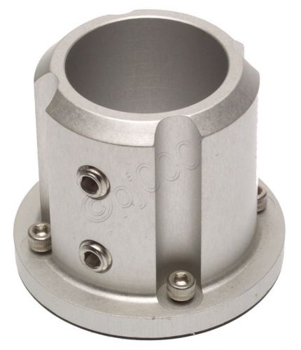
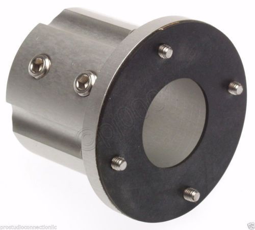
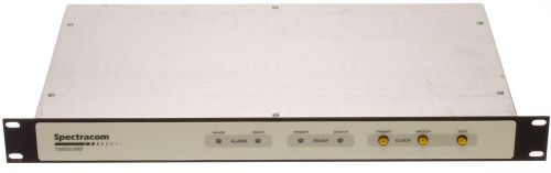
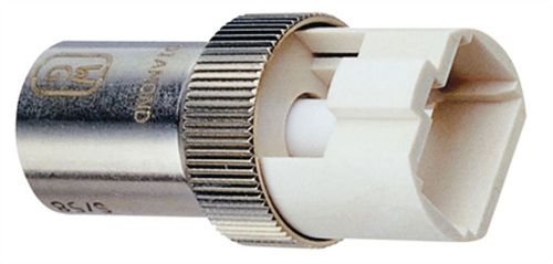
Model | Lucent L115 |
| Manufacturer | Lucent Symmetricom Nokia | ||
| MPN | KS24019 |
Directions
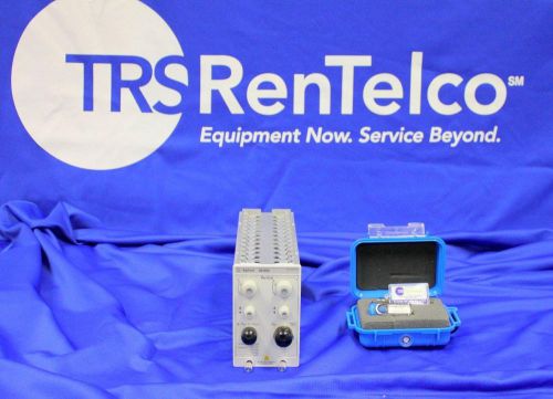
Similar products from Time Providers & Other Time Testing Equipment
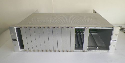
TRAK Systems / TRAK Microwave 9200-3 Expansion Chassis
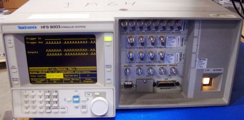
Tektronix VX1405 HFS9003 System With TB, CPU, HFS- 9DG1, 2 HFS-9DG2 USED As-Is
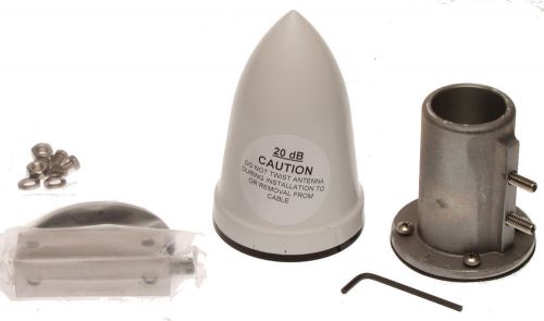
Andrew Maxrad Lucent PCTEL Datum GPS 20dB Active Antenna Telecom Timing w/ Mount
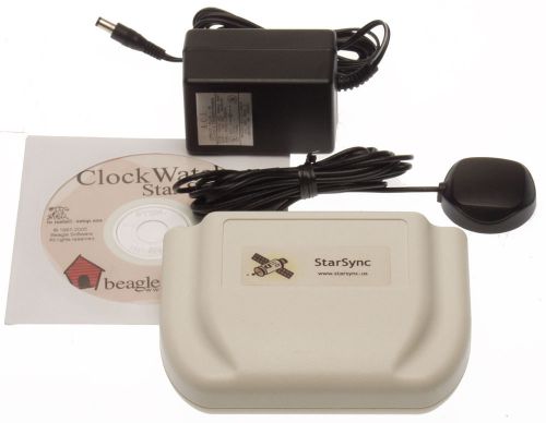
ClockWatch Star Sync External GPS Atomic Time Receiver w/Antenna Beagle Software
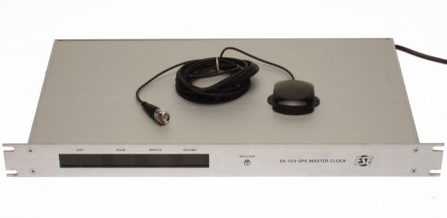
ESE ES-103 GPS Satellite Clock Receiver Clock IRIG-B TC90 TC89 IRIG-B Timecode
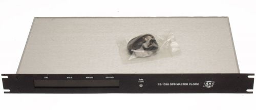
ESE ES-103U GPS Satellite Clock Receiver Clock IRIG-B TC90 TC89 IRIG-B Timecode
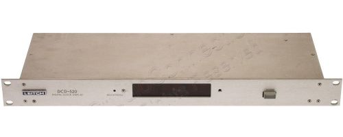
Leitch DCD-520 SMPTE Timecode Broadcast LED Digital Display Clock Rackmount
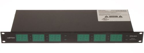
Leitch DTD-5233 5230 Green LED SMPTE/EBU Timecode Clock 1U Dual Display HH:MM:SS
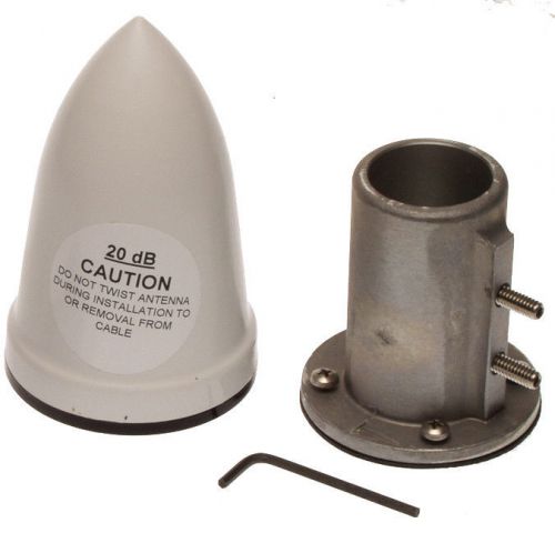
Maxrad Andrew Lucent PCTEL Datum GPS 20dB Active Antenna Telecom Timing w/ Mount
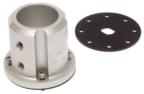
NEW GPS Antenna Outdoor Aluminum Pole Mount Skirt Lucent KS24019 L114 407549245
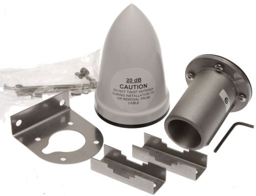
PCTEL GPS-TMG-20 Maxrad Lucent Datum GPS 20dB Antenna w/ Dual Pole Mount Kit
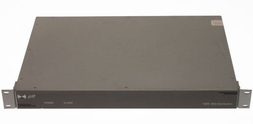
PTF 1205A 1x12 Modulated IRIG-B Distribution Amplifier Precise Time & Frequency
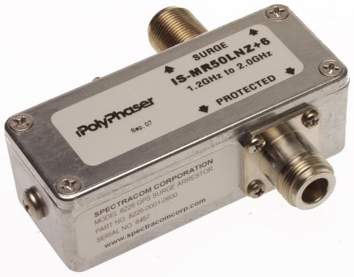
Spectracom 8226 GPS Antenna Surge Protector Downlead Grounding Kit NEW Reg $323
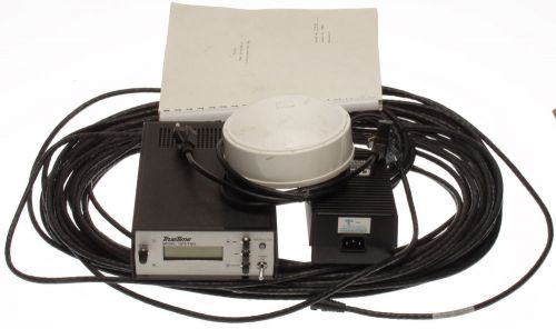
TrueTime Datum GPS-TMD Atomic LCD Clock Time Receiver Trimble Active Antenna 12V
Spectracom 8145 WWVB GPS Source Selector Switch Auto Failover Signal Loss Alarm
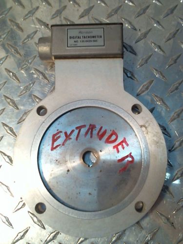
ACRISON DIGITAL TACHOMETER MODEL MPT 135-0429-56C WITH MAGNETIC PICKUP
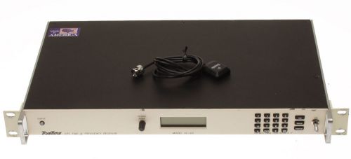
TrueTime Symmetricom XL-DC GPS Timecode Receiver 1/5/10MHz Oscillator IRIG-B
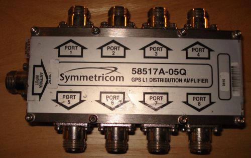
Symmetricom GPS L1 Distribution Amplifier *USED* 8 port
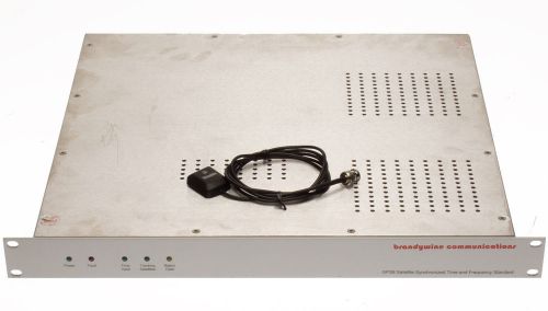
Brandywine GPS-8 Atomic Clock Time Receiver Disciplined 10MHz Oscillator IRIG-B
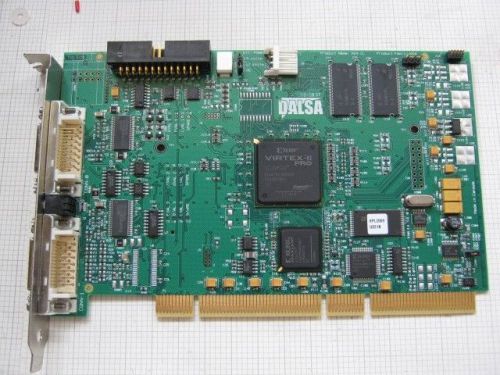
DALSA Coreco Imaging X64-CL iPro 2 CameraLink Frame Grabber OR-64E0-IPRO0
People who viewed this item also vieved
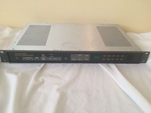
VIDEOTEK DM-141A Frequency agile demodulator - USED Free Shipping!
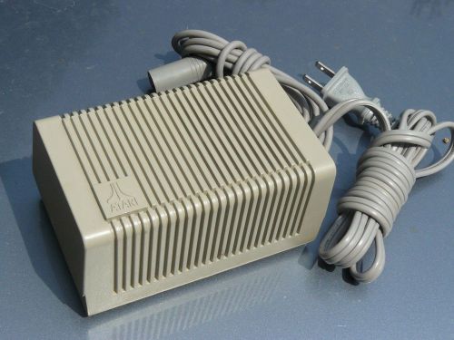
ATARI POWER SUPPLY 1103 VIDEO GAME
GREENLEE ASC-108 ADAPTER, UCI SC
AGILENT 86105D 20G Optical Module for use with 86100D Mainframe
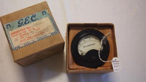
Vintage Ammeter Gauge By G.E.C. Made in England (in box)
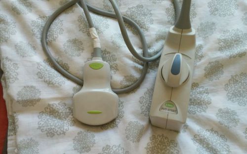
Toshiba PVT-375BT Probe 3.5MHz Apolio Xario Probe Transducer Ultrasound
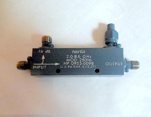
NARDA HP 0955-0098 Directional Coupler Free S&H

-60-125°C green led digital thermometer temp panel meter Temperature Monitor
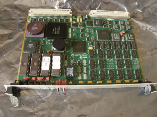
Motorola MVME 147-022 01-W3964B-13B VME Module
DWYER 424 INCLINED-VERTICAL MANOMETER 424-10 PRESSURE MEASUREMENT INSTRUMENT
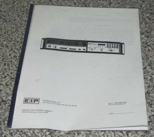
EIP MICROWAVE MODEL 371 MANUAL
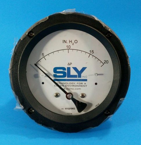
SLY INC. 142AC-00-OO IN. h2O METER CC13
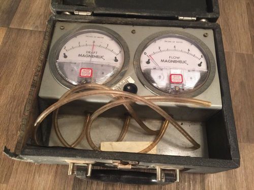
Scott Portable Go/No-Go Tester Draft Magnehelic And Flow Magnehelic
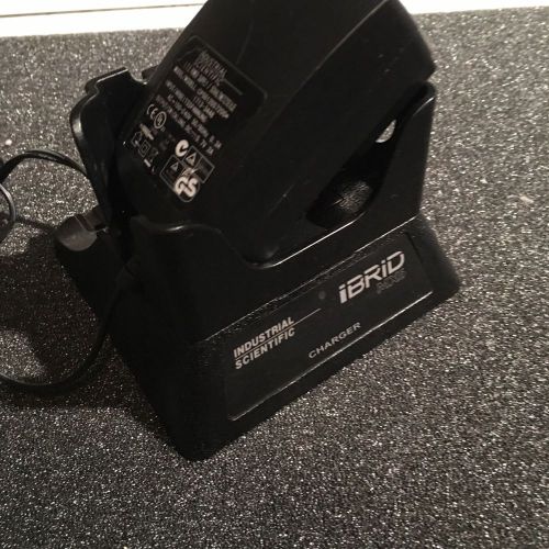
Industrial Scientific Ibrid Mx6 Charging Dock
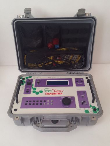
Berkeley Varitronics Sys Gator Transmitter 1820-2100 (30/50/200) MHz 20W Class A
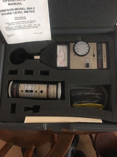
Simpson Sound Measuring System
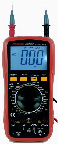
Sinometer VC9808 30-Range Digital Multimeter & LCR Meter A Professional Multi...
Radon Eye RD200 Smart Radon Monitor Detector
By clicking "Accept All Cookies", you agree to the storing of cookies on your device to enhance site navigation, analyze site usage, and assist in our marketing efforts.
Accept All Cookies