


US $550.00
| Condition: |
New: A brand-new, unused, unopened, undamaged item in its original packaging (where packaging is
applicable). Packaging should be the same as what is found in a retail store, unless the item is handmade or was packaged by the manufacturer in non-retail packaging, such as an unprinted box or plastic bag. See the seller's listing for full details.
...
|
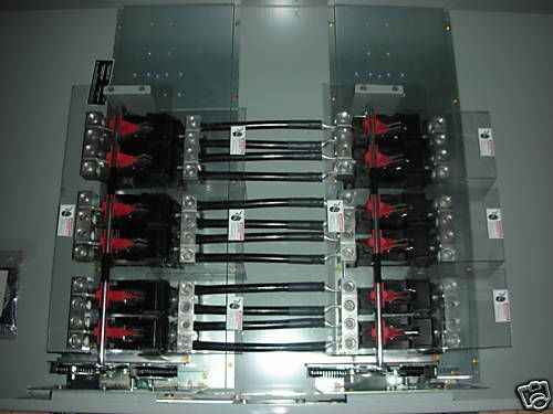
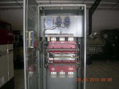
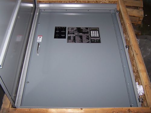
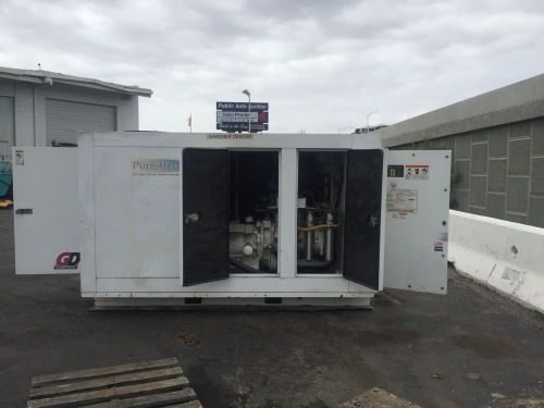
Brand | Erico |
| Model | custom built | ||
| Country of Manufacture | United States |
Directions
Similar products from Transfer Switches
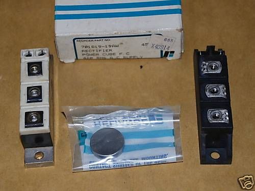
Reliance Electric Power Cube 701819-19AW 70181919AW NEW
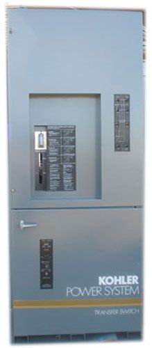
Kohler 600A 480V 3Ph 4W Automatic Transfer Switch Nema1
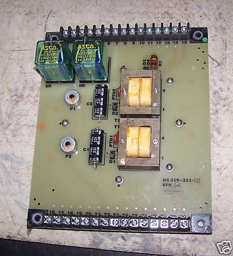
AUTOMATIC SWITCH CO TRANSFER SWITCH BOARD HS 359-323-2
ZENITH ZBTSL40FC-7 400A TRANSFER BYPASS SWITCH 480/277
GE ZENITH CONTROLS 1000A TRANSFER SWITCH ZTGK100FC-7
2000A TRANSFER SWITCH 3 PH STATIC L3 COMMUNICATIONS
1200 600 Volt Manual Transfer Switch In Stock Louisiana
New Cegelec Automation Isolation Switch MTR3
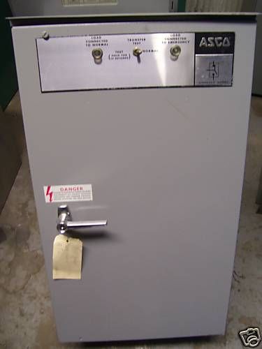
ASCO 150 AMP 120/208 VOLT AUTOMATIC TRANSFER SWITCH
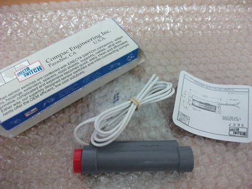
Straight Body Flow Switch Compac Eng. Erecta Switch
Russelectric 3000amp Auto Transfer Switch 120/208v 3ph
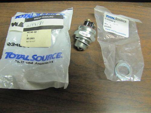
New Total Source Switch Kit N0I40/00 3012821 034600
ASCO 962 AUTOMATIC 800A 480V TRANSFER SWITCH E962380097
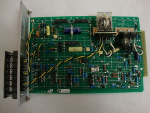
Reliance Static Sequence 0-51874 051874 NEW!
ASCO 800A 480Y277 AUTOMATIC TRANSFER SWITCH F94038097XC
ASCO SERIES 300 260A 480V 3PH AUTOMATIC TRANSFER SWITCH
CAT 150A 277/480V 3PH CTG AUTOMATIC TRANSFER SWITCH
ONAN BT400 400A 480V 4P 60Hz BYPASS TRANSFER SWITCH
UNUSED 400A 480V 3PH4W KOHLER AUTOMATIC TRANSFER SWITCH
People who viewed this item also vieved
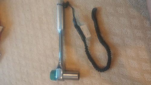
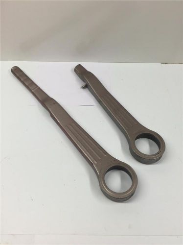
2PC USED 640 CM Lever Hoist Cummalong Puller Replacement Lever 640-127 40663
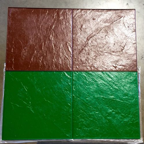
*NEW* 24" x 24" Toscana Slate Rough Stone Texture Mat Set of 2
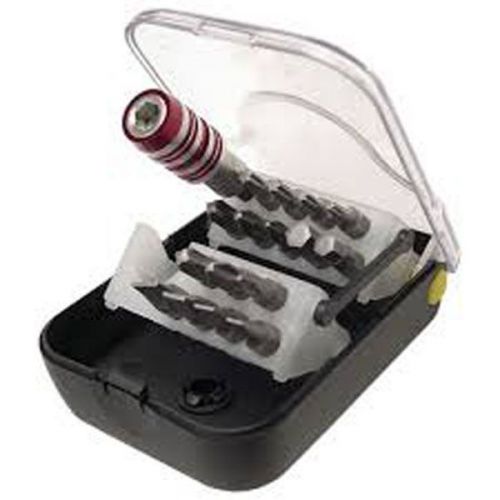
Platinum Tools Belt Clip Bit Set with Holder 16 pcs
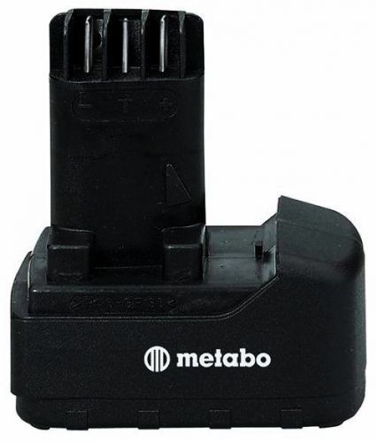
Metabo 631740000 BSP Type 18-Volt 2.4 Amp Hour NiCad Pod Style Battery
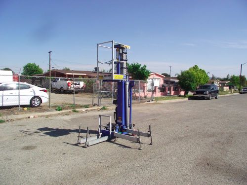
UP-RIGHT INC. MODEL UL-24 MANLIFT - 12V BATTERY OPERATED - 24' LIFT HEIGHT
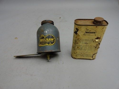
Foley Belsaw sharpener grinder drip mist coolant reservoir
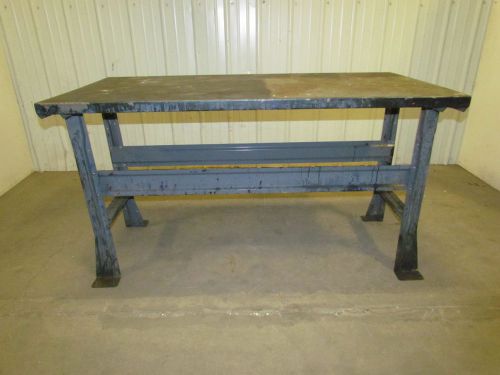
4-Leg Steel Workbench Table Vintage Industrial Gray 60"X30"X33" Height
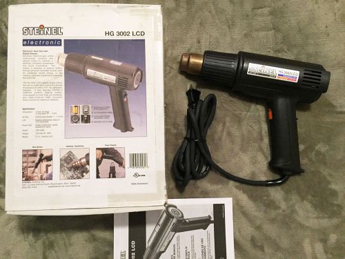
Steinel Heat Gun HG3002 LCD Display - Original Box Like New - NR
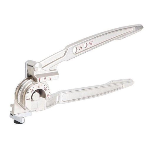
Iwiss 3/8"&1/2" O.D.Tubing 180 Degree Copper Pipe Bending Tool Tubing Bender
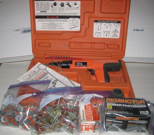
Cobra Ramset .27 Caliber Power Actuated Kit w/ Case 300+ Fastners Manual Brushes
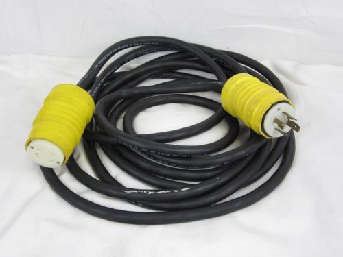
25' Leviton NEMA 125/250 L14-30P/R 3 Pole 4-Wire Grounding 10AWG Power Cable
Twin Screw Air Compressor Gardner Denver 100 Hp Model Number Ewf99B Three Phase
NOS Stone jumping jack rammer tamper boot bellow Part# 47361 XT XM, XD, XJ T12D
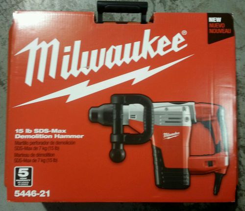
Milwaukee 5446-21 SDS-Max Demolition Hammer NEW with case
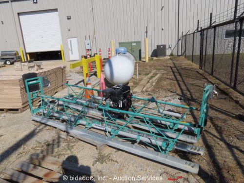
Multiquip WSHE/A Vibratory Truss Screed Honda GX270 Engine 9HP bidadoo
By clicking "Accept All Cookies", you agree to the storing of cookies on your device to enhance site navigation, analyze site usage, and assist in our marketing efforts.
Accept All Cookies