


US $920
| Condition | Used
:
An item that has been used previously. The item may have some signs of cosmetic wear, but is fully operational and functions as intended. This item may be a floor model or store return that has been used. See the seller’s listing for full details and description of any imperfections.
|
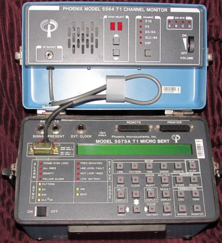
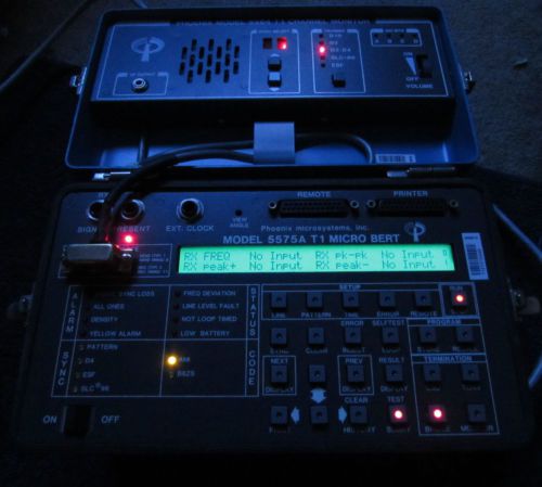
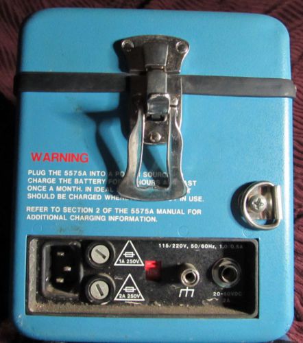
| Seller Notes | “Great condition inside is nice and this comes with manual 1988 and power cord (for 120v)not the original cord. Guaranteed to work.” |
Directions
Similar products from Other Measurement Tools for Telecom
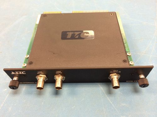
TTC ACterna JDSU 31812 34M Interface Adaptor
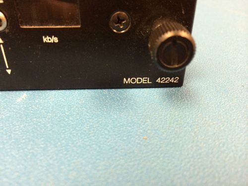
TTC JDSU Acterna 42242 Diphase Interface Adaptor
GL Communication Inc. 9121TB1G8CE ( w/Accy's & Cart)
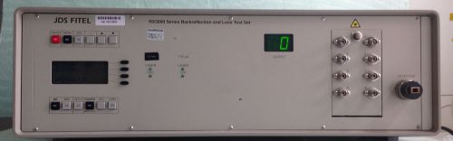
JDSU RX3008+Z0001 ) Backreflect Meter
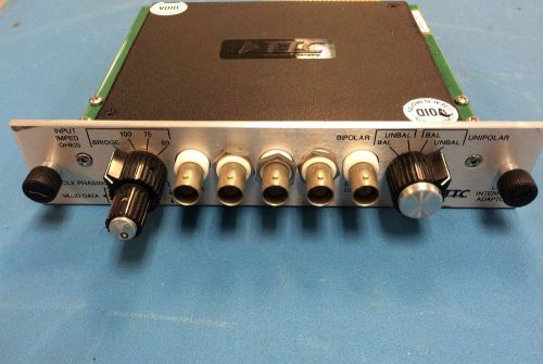
TTC Acterna 40204 Adapter Lab Interface Adaptor
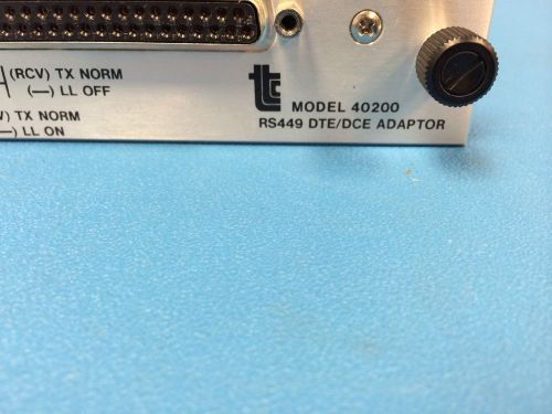
TTC 40200 RS449 DTE/DCE ADAPTOR
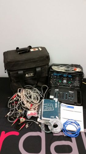
TTC ACTERNA JDSU T-berd 224 PCM ANALYZER W/ 9 OPTIONS AND MANY EXTRAS T1ET9341AA
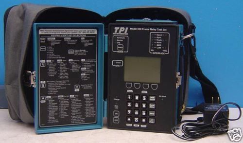
TTC / Acterna TPI 650 Frame Relay Test Set w/SMDS DXI
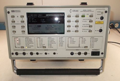
HEWLETT PACKARD CERJAC MODEL 156 MTS SONET MAINTENANCE TEST SET AS-IS
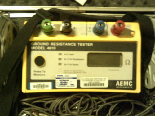
AEMC 4610 with testing kit Ground Resistance Tester
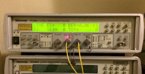
Tektronix ST2400 2.4Gb/s SDH/Sonet Test Set
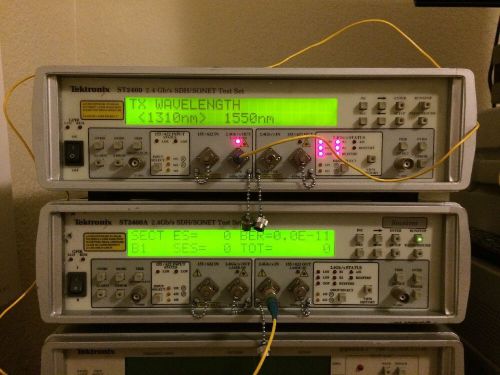
Tektronix ST2400 2.4Gb/s SDH/Sonet Test Set Rx Only
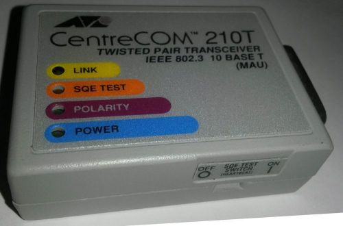
CENTRECOM 210T TWISTED PAIR TRANSCEIVER IEEE 802.3 10 BASE T (MAU)
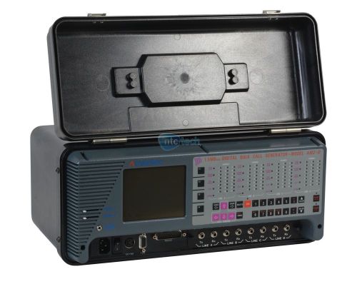
Ameritec AM2-D 1.5MB Digital Bulk Call Generator
Ixia LMOC48SR OC-48c Packet Over SONET/SDH Load Module
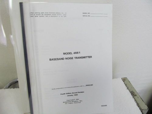
Scientific Atlanta 4661 Baseband Noise Transmitter Instruction Manual (no schem.
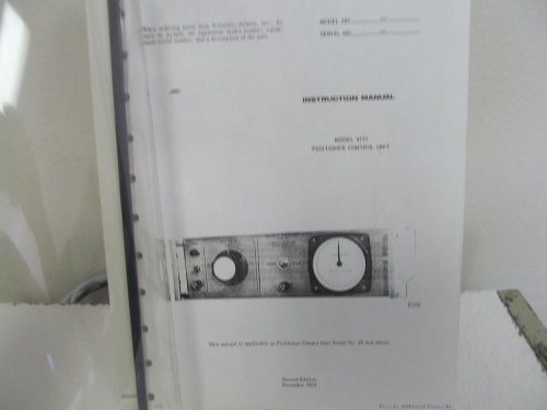
Scientific Atlanta 4111 Positioner Control Unit Instruction Manual
People who viewed this item also vieved
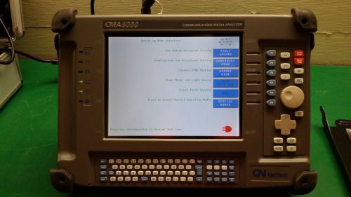
OTDR GN Nettest CMA4000 Fiber Optic Optical Time Domain Reflectometer
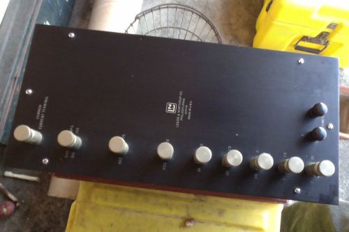
Leeds & Northrup 150 amp shunt box
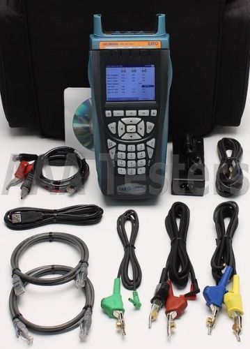
EXFO AXS-200/635i SharpTester Copper VDSL2 ADSL2+ Tester AXS-200 AXS-635 AXS 200
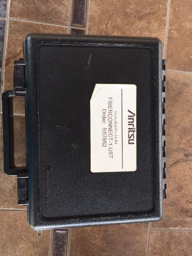
Anritsu Fiberconnect Otdr Bare Fiber Pigtail Kit
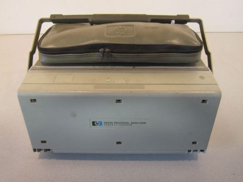
Hewlett Packard Protocol Analyzer 4953A
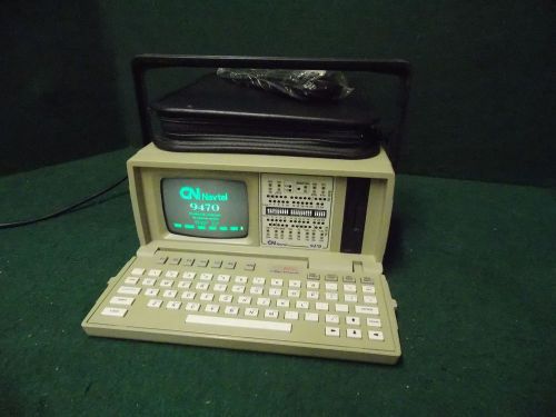
GN Navtel 9470 Protocol Analyzer %
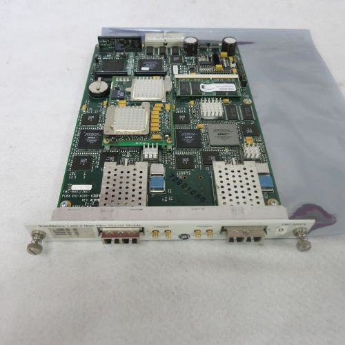
Spirent/Smartbits FBC 3602A 1G/2G 2-Port Fibre Channel SmartMetrics Module/Board
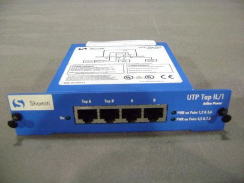
New In Box! Finisar Shomiti THGs Gigabit Protocol Analyzer with Three Taps
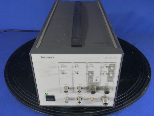
Tektronix 067-0886-03 System M Test Modulator for the 1450
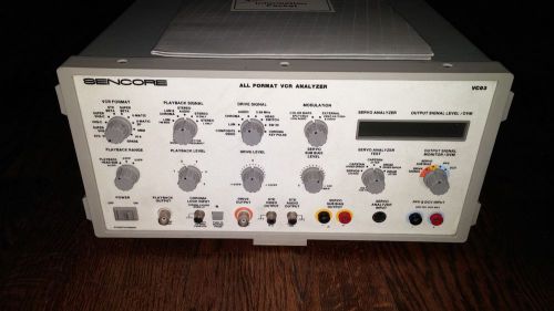
Sencore VC93 All Format VCR Video Analyzer VC-93
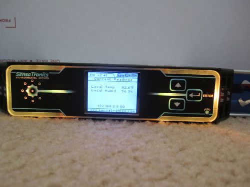
Senturion Rack Mountable Environmental Monitor---FAST SHIPPING--
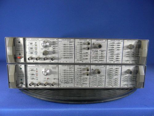
Tektronix 1410 NTSC Generator Mainframe As Is
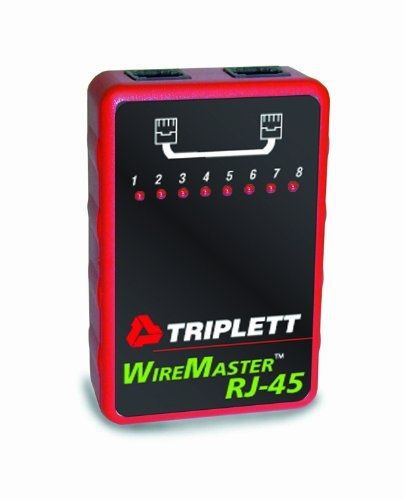
Triplett WireMaster 3251 RJ45 LAN Cable Tester
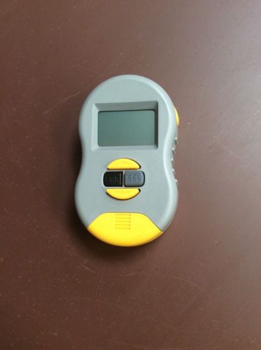
Byte Brothers RWC1000 Main Unit Real World Certifier LAN Cables Networks
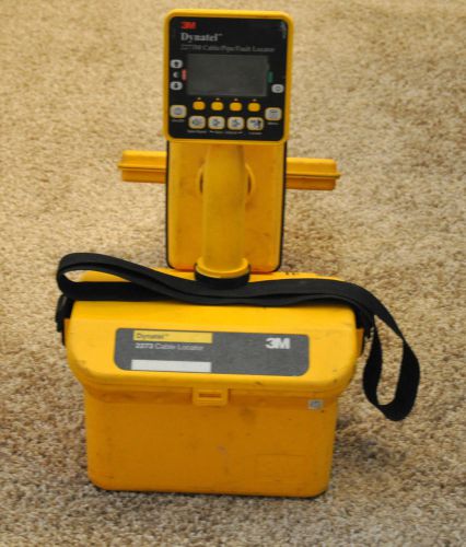
3M Dynatel 2273 Cable Pipe Fault Locator 2273-U3P3
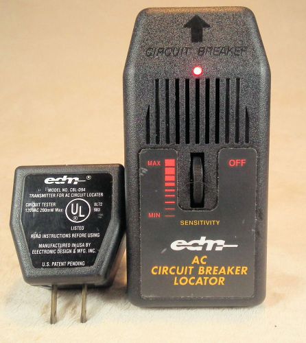
EDM CBL-D94 Breaker Finder system, complete, AC Overcurrent Device Locator
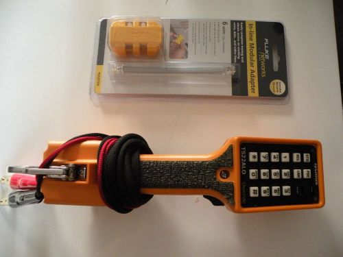
TS22ALO BUTT SET UPGRADED with Fluke banjo adapter
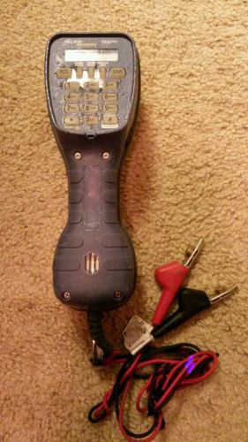
FLUKE NETWORKS TS52 PRO BUTT SET TELEPHONE LINEMAN'S TEST ABN
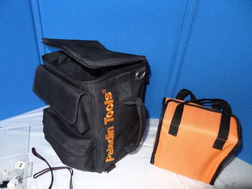
Paladin Ultimate Tech Tool Kit PA4932
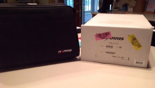
HARRIS TS250 #25475-000 IN SOFT CASE
By clicking "Accept All Cookies", you agree to the storing of cookies on your device to enhance site navigation, analyze site usage, and assist in our marketing efforts.
Accept All Cookies