US $299.99
| Condition | Seller refurbished
:
An item that has been restored to working order by the eBay seller or a third party not approved by the manufacturer. This means the item has been inspected, cleaned, and repaired to full working order and is in excellent condition. This item may or may not be in original packaging. See the seller’s listing for full details.
|
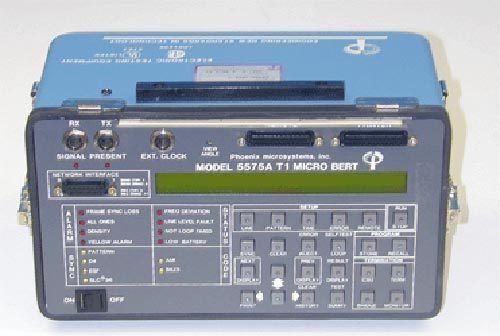
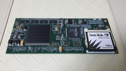
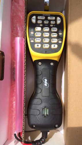
| Seller Notes | “The battery in the unit is not included, however the unit can run off a line cord. The units are guaranteed to work for 30-days, parts and labor, excluding freight. There is no front cover.” |
Directions
Similar products from Other Measurement Tools for Telecom
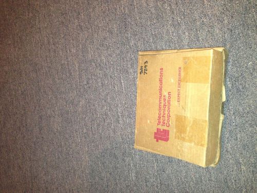
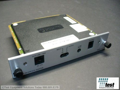
TTC 30678A DDS DS0A/B Interface Adaptor Module - Black
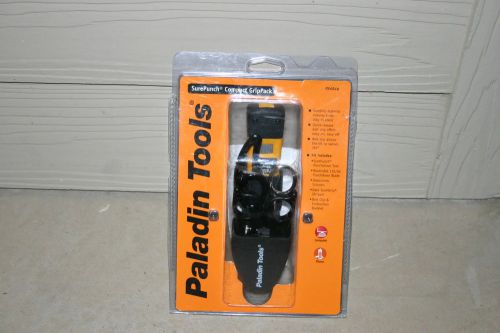
Paladin Sure Punch Compact Grip Pack PA 4946 New in original packagaing
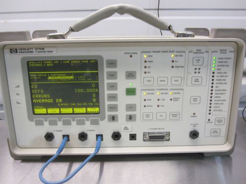
HP Agilent 37701B T1 Datacom Tester Bit Error Rate Testing
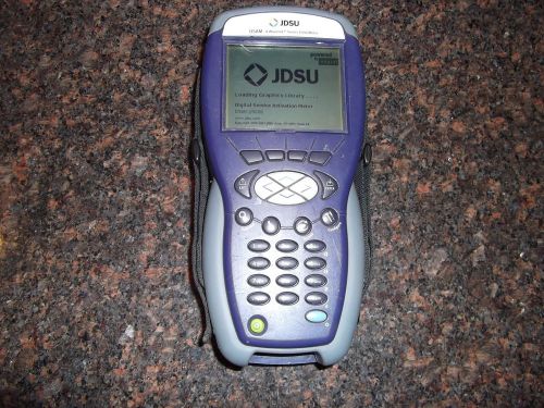
JDSU ACTERNA DSAM 2500B CATV CABLE HANDHELD FIELD METER TEST SET VOIP DOCSIS 2.0
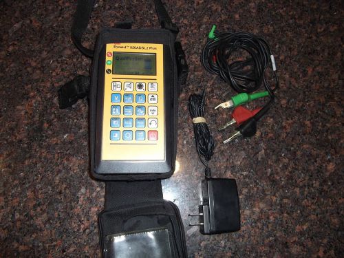
3M DYNATEL 950ADSL2 PLUS DSL ADSL2+ QUALIFICATION TEST SET LEADS CASE CHARGER
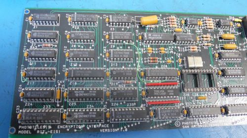
Phototelesis Model RIT-E1S1 Encryption Interface 1 Version 1.0
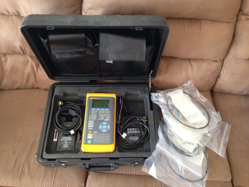
Fluke DS3port Plus Handset ATM Tester
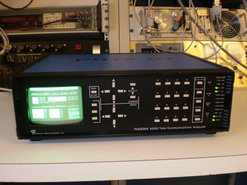
PHOENIX 5500 TELE-COMMUNICATIONS ANALYZER
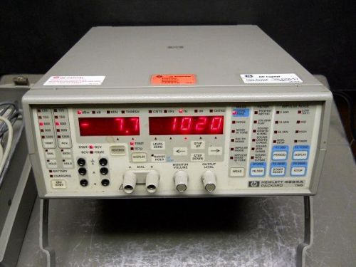
Hewlett Packard HP 4934A TIMS Transmission Impairment Measuring Set w/ battery
Acterna TTC JDSU 40202 Interface DTE/DCE ID # 5231 TEST
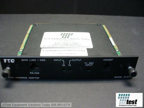
Acterna TTC JDSU 41440A T-1/Fractional T-1 Interface for 6000A ID #14800 TEST
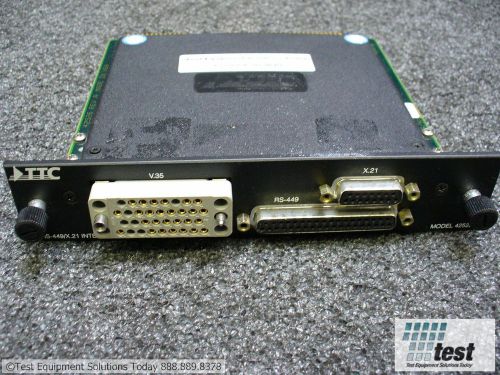
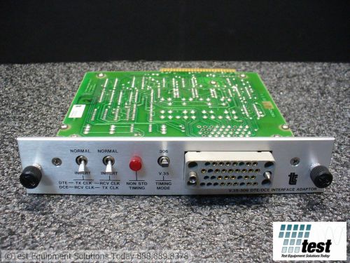
Acterna TTC JDSU 42522 DTE/DCE Interface V.35/306/RS-449/X.21 ID #23840 TEST
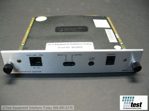
Acterna TTC JDSU 41440 T1/Fractional T1 Interface for TTC 6000A ID #21825 TEST
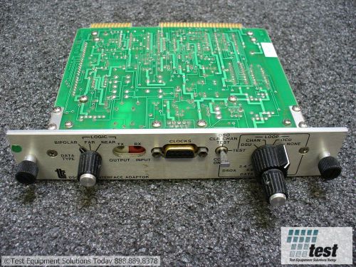
Acterna TTC JDSU 30481 DSO/DSOA Interface Adapter for Fireberd ID #23850 TEST
Acterna TTC JDSU 41440 T1/Fractional T1 Interface for TTC 6000A ID #21823 TEST
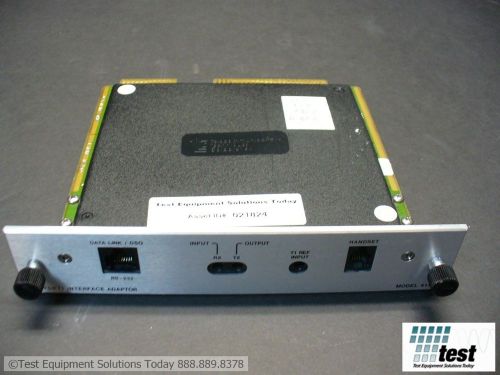
Acterna TTC JDSU 41440 T1/Fractional T1 Interface for TTC 6000A ID #21824 TEST
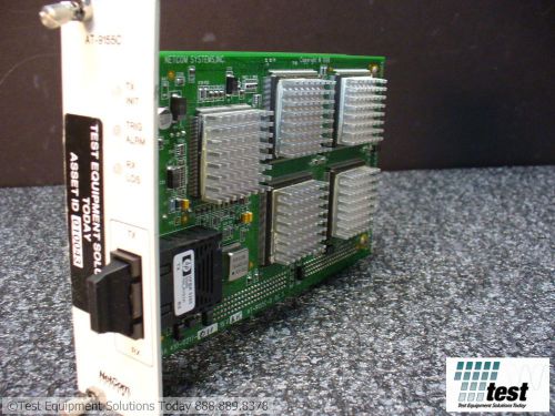
Spirent AT-9155C 850nM Multimode Module OC3 ID #10043 TEST
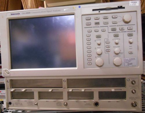
Tektronix CSA 8000 Sampling Oscilloscope
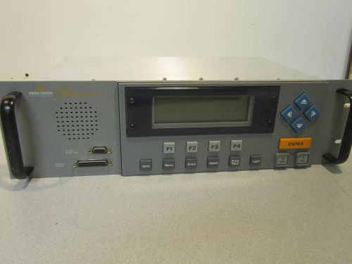
Sunrise Telecom Broadband Sweep Ingress Analyzer 85963A 3010H OPT ABA 052 061
People who viewed this item also vieved
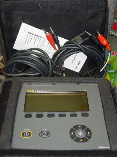
Tektronix TS100 TelScout TDR Cable Fault Detector With Cable option 1, new bat.
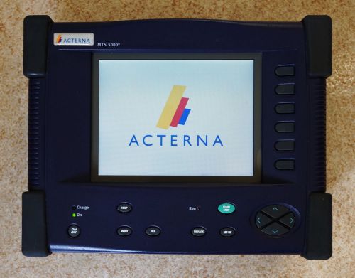
Acterna / Wavetek mts5100e OTDR
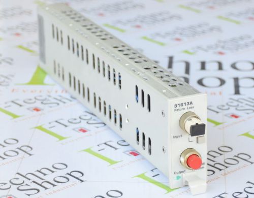
Agilent 81613A Return Loss Module with integrated Laser Source HP EMS Offer!!!
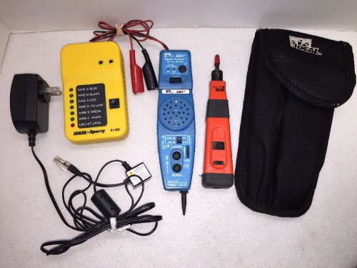
Ideal ABS Signal Thrower 62-184 & Sperry 61-530 W/ Case & More Used
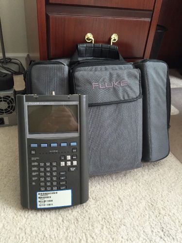
A95659 Fluke 675 LANmeter Ethernet/ Token Ring, LAN/WAN Analyzers
IXIA 400 4-slot Traffic Generator Performance Analyzer
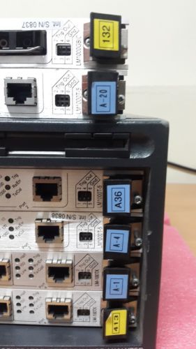
XD Security Module (ACC-3603A) for LAN-3321A, LAN-3327A
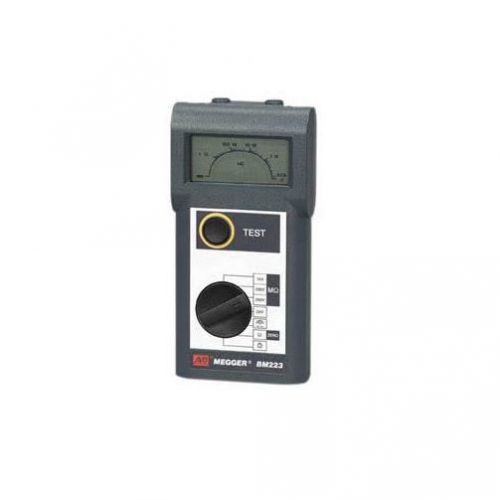
Megger Insulation and Continuity Tester BM223 New In Original Packaging
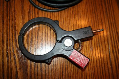
3M Dynatel 3001 Induction Clamp Dyna-Coupler with 9011 coupler extension cord
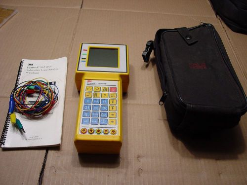
3m Dynatel 965dsp 965-dsp V4 Version BASIC WITH CASE MANUAL LAEDS
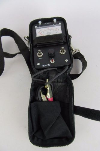
METRO TEL MT-8455 L2 Voltmeter Ohmmeter
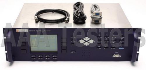
Acterna WWG Wavetek SDA-5500 Stealth Reverse Sweep Manager 4 SDA-5000 SDA5500
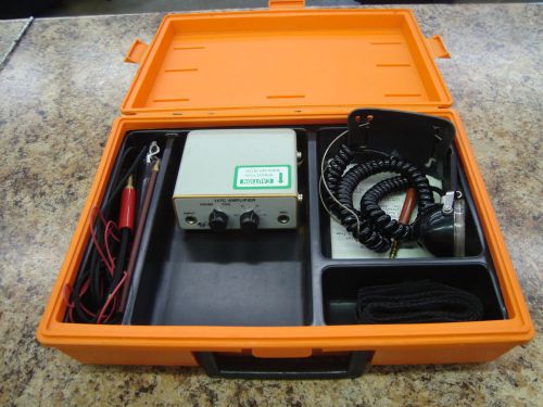
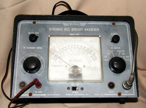
Win-Tronix Dynamic AGC Circuit Analyzer Model 825
Harris Dracon TS 22 Telephone Butt Set Tester
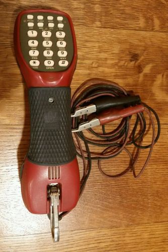
Linemans Telephone Chesilvale Electronics Butt Test Set Phone Line Tester Red
Tempo PE930 BUTT TESTER-EXCELLENT CONDITION-WORKS GREAT!
By clicking "Accept All Cookies", you agree to the storing of cookies on your device to enhance site navigation, analyze site usage, and assist in our marketing efforts.
Accept All Cookies