


US $469.00
| Condition: |
Used: An item that has been used previously. The item may have some signs of cosmetic wear, but is fully
operational and functions as intended. This item may be a floor model or store return that has been used. See the seller’s listing for full details and description of any imperfections.
...
|
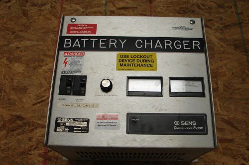
Model | DCT48-12-A643 |
| Manufacturer | SENS |
Directions
Similar products from Electrical Fuses
24 pcs Resettable PTC Polyfuse, MF-R Series by Bourns, P/N MF-R135-2
25 pcs 5A Fuses, 125V axial by Belfuse. 6A
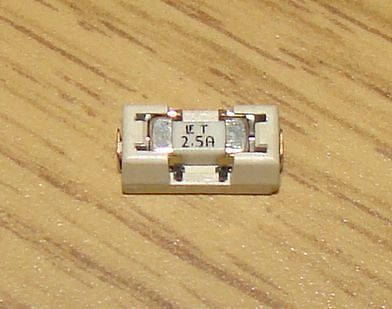
12 pcs 2.5A Slow Blow smt fuse with holder 1A1b
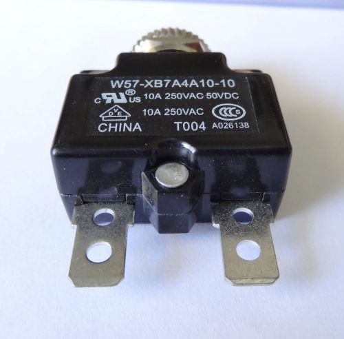
1 pc, 10A resettable circuit breaker by TYCO, P/N 1423675-7
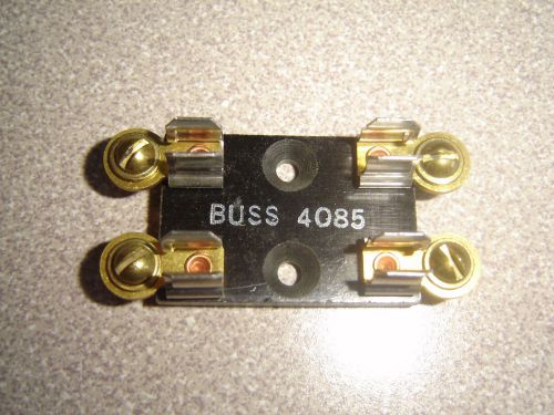
Buss 4085 Dual Fuse Block Holder, 4 Terminal Screws 1/4" x 1-1/4" for 3AG fuses
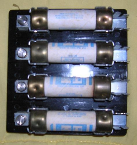
Used MARATHON H40QB FUSE BLOCK 4742178 WITH NLN 40 FUSES
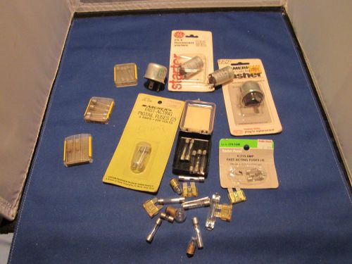
LOT OF OVER 35 VINTAGE AUTO FUSES AND FLASHERS BULBS STARTER
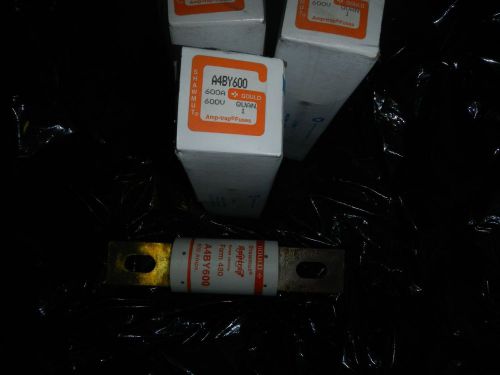
Gould Shawmut A4BY600 600AMP FUSE 600Volt AMP-TRAP KRP-C600 NEW
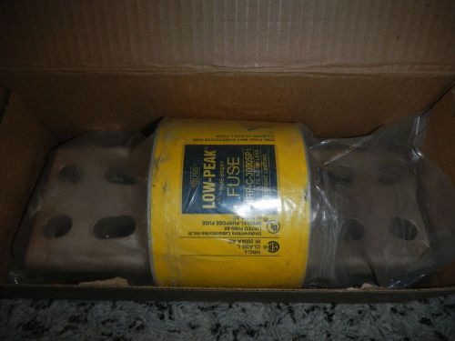
BUSSMANN KRP-C-3000SP 3000 AMP FUSE BUSS Replaces A4BQ3000 , CLASS L NEW
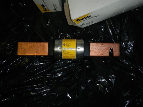
Bussmann LPS-RK-225SP 225Amp FUSES (3PIECES) 600Volt Dual Element,Time Delay NEW
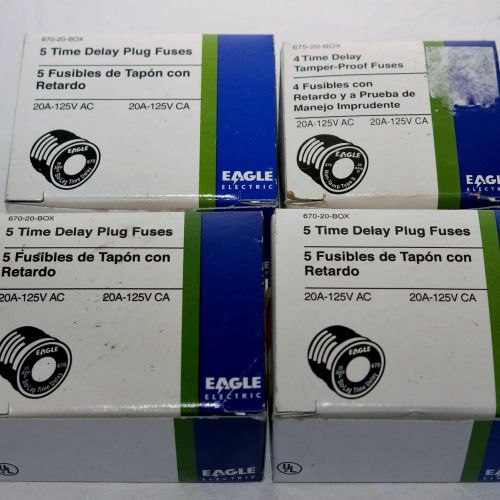
Eagle Electric Time Delay Plug Fuses 20A-125V AC 20A-125V-CA Lot of 17
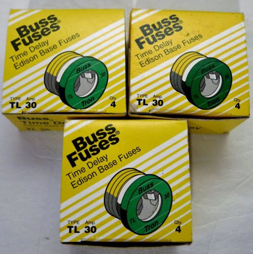
Buss Fuses Time Delay Edison Base TL30 Lot of 11
NEW FERRAZ SHAWMUT OTN15 SUPER ONE TIME TYPE P 15A AMP 250V-AC FUSE B408526
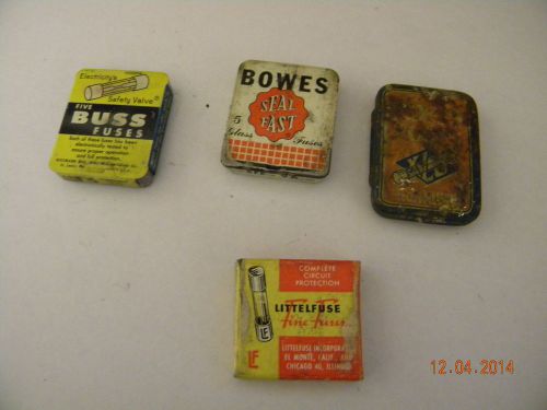
LOT OF FOUR VINTAGE AUTOMOTIVE FUSE BOXES BOWES, BUSS , LITTELFUSE & EXELLO
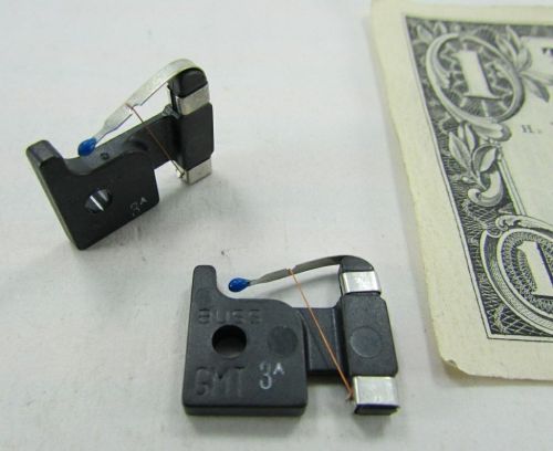
10 Cooper Bussmann 3A 125V AC/DC Fast Acting, Trip Indicating Fuses GMT-3A Blue
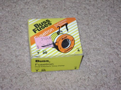
BUSS FUSES / FUSETRON / DUAL ELEMENT / TIME - DELAY
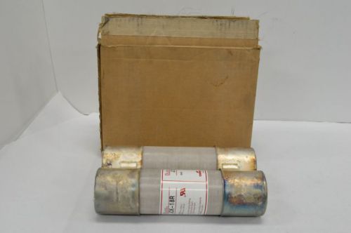
COOPER BUSSMANN JCK-18R DOUBLE BARREL HIGH VOLTAGE 390A 2.54KV-AC FUSE B211688
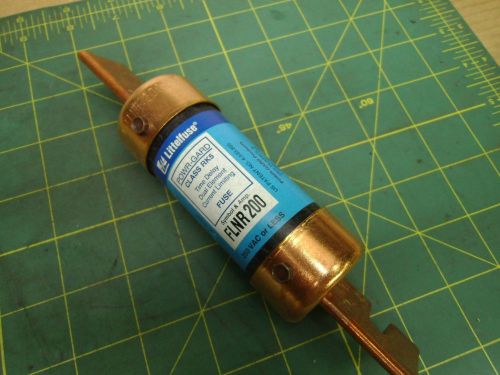
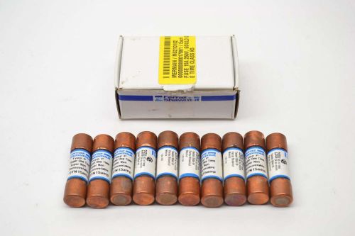
LITTLE FUSE FLNR200 CLASS RK5 TIME DELAY FUSE (QTY 1) #J55253
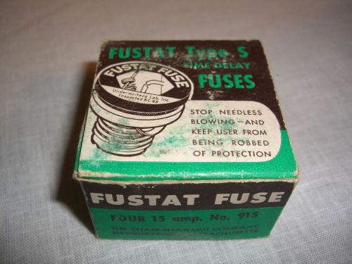
Fustat Type S Time Delay Fuses 4 In Box New 15 amp No. 915
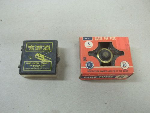
VINTAGE / ANTIQUE 20 AMP FUSES $ PIPE TAPE JOINT SEALER NEW
People who viewed this item also vieved
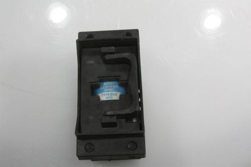
BUSSMANN TPHCS800-E FUSE HOLDER W/ TPH-600 600 A 170V FUSE
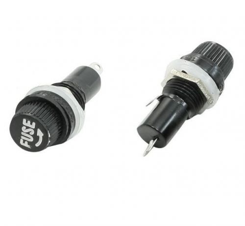
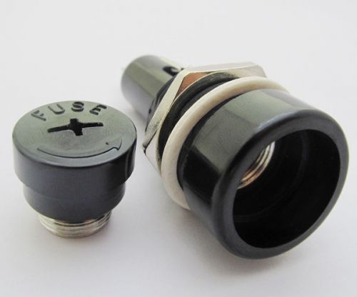
10PCS CB radio Auto Stereo Chassis Panel Mount AGC Glass Fuse Holder new
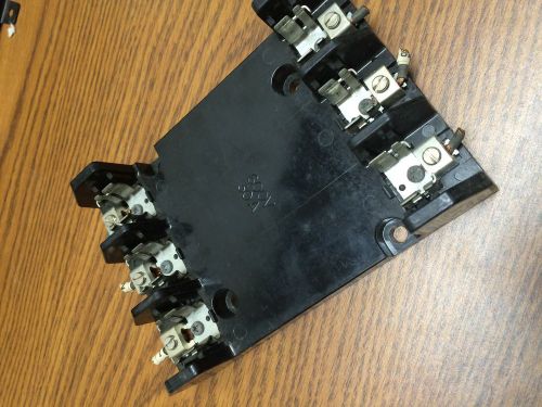
Used Marathon 41100832 fuse block 600V 30A 3P holder R6F30A3B
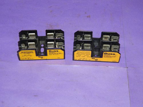
Lot of 2 bussmann BM6032SQ Fuse Holder 2 pole 30 amp 600 volt
1pcs Fuse Holder for 10 x 38mm 10x38 Fuse R3-41 30A 600V
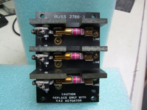
Buss 2788-3 blown fuse indicator with (3) Buss KAZ acctuator cartridges
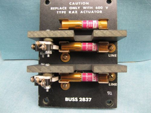
Buss 2837 2 pole blown fuse indicator with (3) actuators
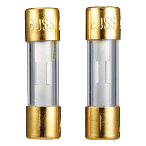
6 Fuses 3 Sets RadioShack 32V 50A Heavy Duty Gold-Plated Fuses Model: 270-0128
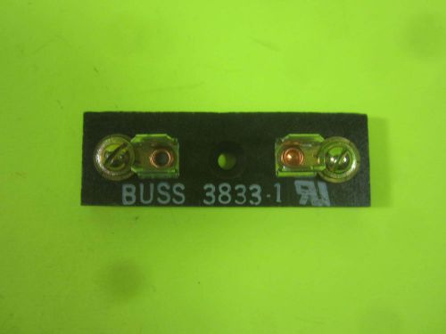
Buss Fuse Blocks -- 3833-1 -- New
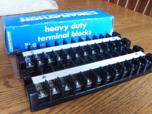
Two New Marathon 1512STD Heavy Duty Terminal Block 12 Terminals 75 Amp 600 Volt
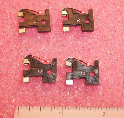
QTY (25) AX1B-10A SOC 10A 125V ALARM INDICATOR FUSE GMT-10A TYPE
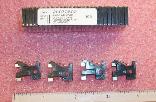
QTY (100) AX1B-10A SOC 10A 125V ALARM INDICATOR FUSE GMT-10A TYPE
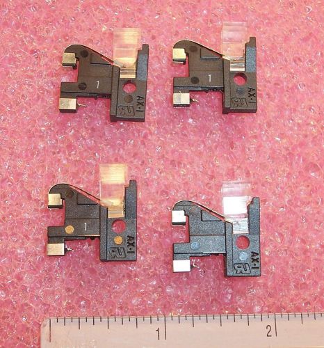
QTY (100) AX1-1A SOC 1A 125V ALARM INDICATOR FUSE W/ SAX COVER GMT-1A TYPE
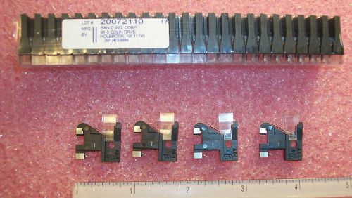
QTY (25) AX1-1A SOC 1A 125V ALARM INDICATOR FUSE W/ SAX COVER GMT-1A TYPE
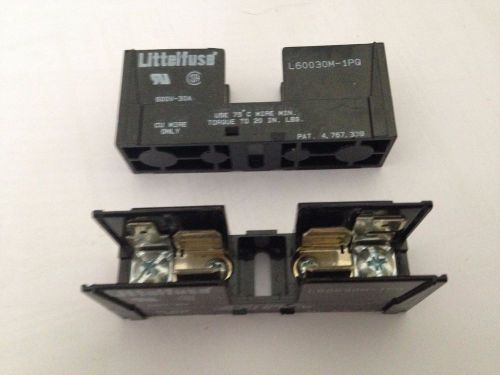
Littlefuse Fuseholder L60030M-1PQ 60V 30A Class M Single Fuse Lot of 2
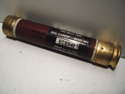
BULLET ECSR40 QUANTITY! TESTED! CLASS RK5 TIME DELAY FUSE
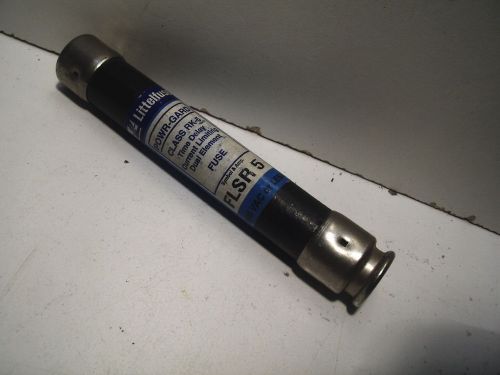
LITTELFUSE FLSR5 FLSR 5 TESTED! TIME DELAY FUSE
By clicking "Accept All Cookies", you agree to the storing of cookies on your device to enhance site navigation, analyze site usage, and assist in our marketing efforts.
Accept All Cookies