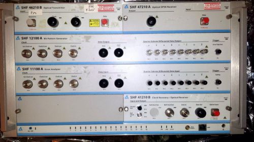
Description of available plug-ins This is an overview of the plug-in units that are fitted into the SHF 10000 A Mainframe. All plug-ins can be fitted or exchanged on site, except where stated otherwise. Further details about each plug-in is available in its operating manual. Full details about the use of the software for the plug-ins are available in the SHF BERT Software Manual. BERT Control software is included (requires an external computer with Ethernet) SHF 12100A bit pattern generator This is a broadband bit patter generator which operates from 6Gbps up to 50Gbps. The bit rate is determined by the clock frequency; it can either be operated in half-clock mode, where a 25GHz clock signal produces 50Gbps signals, or in full-clock mode, where a 50GHz clock produces 50Gbps signals. It allows the production of PRBS signals with pattern lengths of 271, 29-1, 211-1, 215-1, 220-1, 223-1, 231-1. User-programmed patterns with lengths up to 128Gbit can also be loaded into the instrument. Due to design constraints, this plug-in can only be fitted at the factory. Options Four subrate data channels are fitted which provide quarter-shifted PRBS data streams with a bit rate of 1.5…12.5Gbps. SHF 11100A error analyzer This is the counterpart to the SHF 12100 A bit pattern generator. It has broadband operation from 6 to 50Gbps and offers high sensitivity and a wide clock phase margin. Due to design constraints, this plug-in can only be fitted at the factory. Options Inputs to analyze four subrate quarter-shifted PRBS signals with a bitrate of 1.5…12.5Gbps are also fitted. SHF 41210 A optical/electrical converter / clock recovery unit The SHF 41210 A is an optical receiver and clock recovery unit. With both options fitted, they are connected internally so that the electrical data and the recovered clock signal are available from the outputs. It is still possible to use both options alone. The optical receiver converts optical signals with a bit rate up to 50 Gbps into electrical signals. Broadband operation is possible and the wide output dynamic range combined with excellent pulse behaviour makes the device ideal for optical system research. The clock recovery extracts a clock signal at a frequency half of the incoming bit rate from an electrical data signal at a nominal bit rate of about 40 Gbps or about 43 Gbps. It contains two separate VCOs which allow operation in a standard mode at 39.81 Gbps or in an FEC mode to cover FEC bit rates of 42.65 Gbps or 43.01 Gbps respectively. Two reference frequencies are included as standard. The clock recovery option does not support broadband operation. SHF 46210 A optical transmitter A flexible and comprehensive high performance solution for electrical to optical signal conversion. The SHF 46210 A can convert input electrical NRZ signals into optical NRZ, RZ and CS-RZ signals in either ASK or DPSK formats. NRZ conversion offers broadband operation up to 50Gbps; the other conversion methods can be used between bit rates of 36…44Gbps. SHF 47210 A DPSK receiver DPSK optical receiver configured with a delay interferometer for ~43 Gbps operation. Includes automatic tracking mode for locking onto laser wavelength. 1. Detailed Specification Follow SHF 10000 A BERT Mainframe 2. SHF 11100 A Error Analyzer Plug-in. Specifications Parameter Unit Min. Typ. Max. Comment Data input Bit rate Gbps 6 50 input AC coupled; DC coupled on request (ground referenced CML, 0…-500mV) S11 dB -10 Sensitivity mV 50 150 standard with DFF Clock phase margin ° 200 Threshold adjustment mV -300 300 0.5mV steps Subrate data inputs (optional) Gbps 1.5 12.5 sensitivity: 100mV Clock input Frequency GHz 3 6 25 50 half clock full clock Input level dBm 0 4 Phase adjustment ps 0 160 0.1ps resolution Trigger (gating) LV TTL Clock outputs Frequency clock clock/2 sel sel: can be switched between bitrate/N, where N=16,32,64,128,256,512 Output level mV 400 600 S11 dB -10 System Data patterns 27-1, 29-1, 211-1, 215-1, 220-1, 223-1, 231-1 User-programmable pattern Mbit 128 Back to back Q factor linear dB 25 28 measured with SHF 12100 A 3. SHF 12100 A Bit Pattern Generator. Specifications: Parameter Unit Min. Typ. Max. Comment Bit pattern generator Bit rate Gbps 6 50 Output level mV 400 500 adjustable by up to -3dB with DFF (not adjustable) Jitter (RMS) fs 500 Rise/fall time ps 10 20%...80% Clock input frequency GHz 3 6 25 50 half clock full clock Clock outputs clock clock/2 sel sel: can be switched between bitrate/16, bitrate/32, … bitrate/512 and wordframe (wordframe only SHF 12100 A) 2x Wordframe outputs mV 500 / 3300 Only SHF 12100B Error Trigger LVTTL Subrate data outputs (Option 010) Gbps 1.5 12.5 Output level mVpp 250 1000 DC bias mV -1000 1000 in 10 mV steps Subrate data outputs (Option 020) Gbps 3 25 350 mVpp fixed output level Patterns Data patterns 27-1 29-1 211-1 215-1 220-1 223-1 231-1 User-programmable pattern Mbit 128 Back to back Q factor linear dB 25 28 measured with SHF 11100 A 4. SHF 46210 B Optical Transmitter Plug-In. Specifications. Data input and output Parameter Unit Min. Typ. Max. Conditions Optical parameters Wavelength range C- and L-band Insertion loss dB 10 11 connector to connector, maximum transmission without modulation DC Extinction ratio dB 40 measured on cascaded device Return loss dB 50 without optical connector Chirp (Alpha parameter) Positive slope Negative slope 0.03 -0.01 0.1 -0.1 small signal measurement method Electrical and electro-optical parameters Electro-optical bandwidth of Data modulator GHz 30 -3dB electrical Bit rate RZ Data Gbps 36 2 44 50 Drive amplifier electrical return loss Data Clock pulse RZ dB -10 -10 ASK-Mode operation Drive amplifier input level Data input RZ clock input Vpp (dBm) 0.35 (-5) 0.5 (-2) 0.45 (-3) 0.6 (0) 0.6 (0) 1.2 (6) Dynamic extinction ratio NRZ RZ CS-RZ dB 11 12 12 13 14 14 measured between data ‘1’ and long sequence of ‘0’ Dynamic signal to noise ratio NRZ RZ CS-RZ 15 18 16 Output rise and fall times NRZ ps 9 10 20%…80% as displayed on oscilloscope Pulse width (FWHM) RZ CS-RZ ps 12 15 measured with 70 GHz detector and 70 GHz sampling scope Output timing jitter <RMS> NRZ RZ CS-RZ ps 1.0 0.4 0.4 1.2 0.5 0.5 total RMS jitter measured with Agilent Mainframe 86100A + 70 GHz plug in 86118A + precision timebase 86107A Position of crossing point @ NRZ % 45 50 55 DPSK mode operation Drive amplifier input level Data Clock pulse RZ Vpp (dBm) 0.6 (0) 0.5 (-2) 0.6 (0) 1.0 (4) 1.2 (6) Phase modulation by 2 V? drive Rad 0 ? Auto-bias control (ABC) Dither signal frequency kHz 10 5. SHF 47210 A DPSK receiver. 6. SHF 41210 A Clock Recovery with Optical Receiver. Specifications Parameter Unit Min. Typ. Max. Conditions Connector Types Input impedance ? 50 Data Input ? 50 Clock Output ? 50 External Reference Input ? 50 Input voltage mVpp 40 800 Output voltage mVpp 400 600 1000 Operating bit rate range Gbps 39.8 41.6 41.6 43.1 Band 1 Band 2 Internal Reference Clock 1 MHz 622.0800 39.81312 Gbps Internal Reference Clock 2 MHz 666.5143 42.65692 Gbps Internal Reference Clock 3 MHz 672.1627 43.01841 Gbps Input/output return loss dB 10 Option OE – Optical receiver Parameter Unit Min. Typ. Max. Comment Wavelength range C and L band High frequency 3dB point GHz 30 Low frequency 3dB point kHz 30 Conversion gain mV/mW 350 450 at 1550 nm, AC-coupled output Receiver sensitivity dBm -9 Output saturation voltage (peakpeak) V 5 6 Rise/fall times ps 9 10 10…90% Optical input power dBm 13 CW
By clicking "Accept All Cookies", you agree to the storing of cookies on your device to enhance site navigation, analyze site usage, and assist in our marketing efforts.