US $160
Directions
Similar products from Other Alert Systems & Accessories
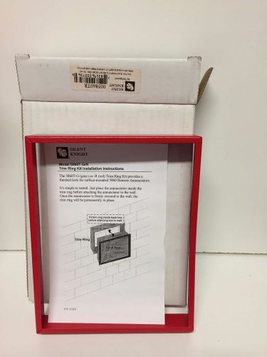
New Silent Knight 5860TR Trim Ring In Red For a 5860R
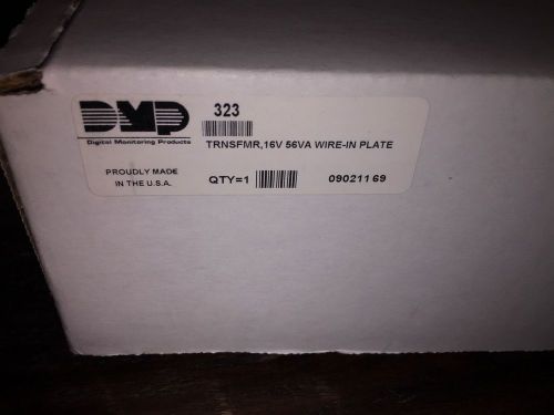
DMP 323 16V 56VA Wire-In Plate Transformer - Digital Monitoring Products
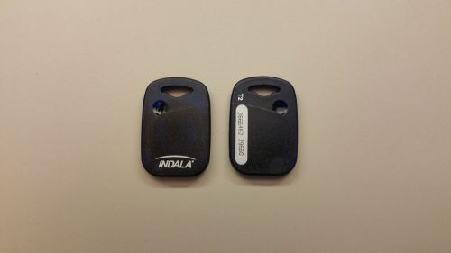
INDALA FLEXKEY HONEYWELL PX-115-I ACCESS KEY FOBS PX115I 4010X
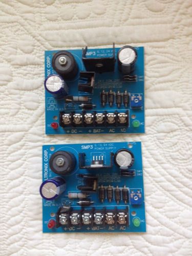
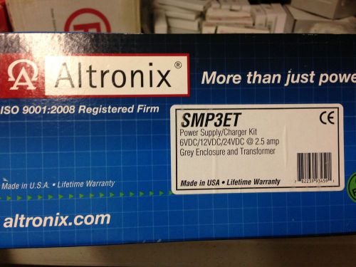
Altronix Smp3 Power Supply 12vdc ( package of 2 units )
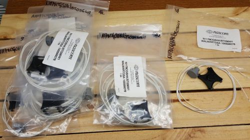
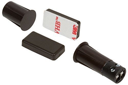
Lot of 12 Nascom N1178CGSHK/ST036 STUBBY SWITCH/SHARK MAGNET SET
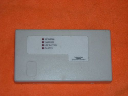
INOVONICS FA-401 FA401 RECEIVER USED WORKS GREAT. RELAY CONTACT ALARM SECURITY
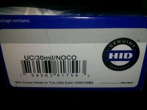
FARGO UltraCard PVC cards, 30 mil - Box of 500 081754
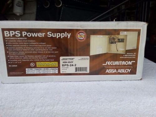
Securitron BPS-24-2 Power Supply Lockbox BPS242 Assa Abloy 24VDC - 2 Amp
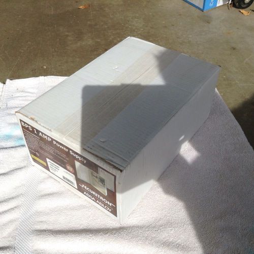
Securitron BPS-24-1 24VDC power supply

Securitron TS-4T Touch Bar Sensor
Securitron TS-2-LS Touch Sensor
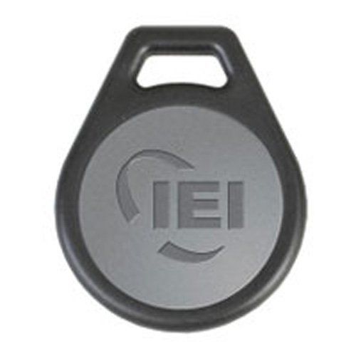
Linear PROXKEY Proxkey Key Fob For Proxpoint
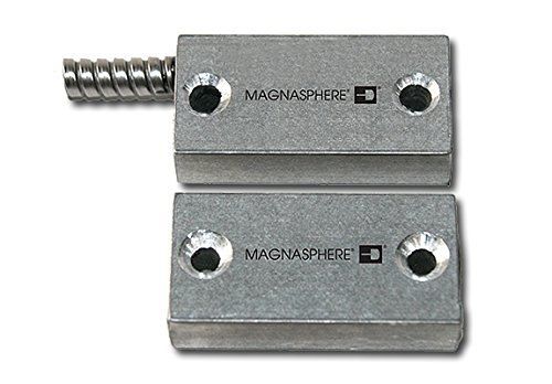
MAGNASPHERE MSS-302S Surface Mount Door Contact with 2 Switches, 2 Open Loop, UL
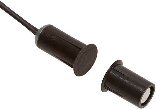
Nascom N1175B/ST Recessed Mini Stubby Press Fit Switch/Magnet Set, Wire Leads,
Nascom NC1175TB/ST Recessed Stubby Terminal Press Fit Switch/Magnet Set, 3/8"
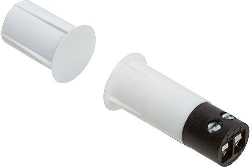
Nascom NC1175TW/ST Recessed Stubby Terminal Press Fit Switch/Magnet Set, 3/8"
Nascom N175W/ST Recessed Stubby Press Fit Switch/Magnet Set, Wire Leads, 3/8"
People who viewed this item also vieved
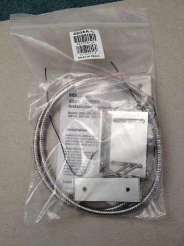
Sentrol 2505A-L Security 2500 Series Industrial Surface Mount Contact Overhead
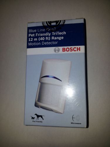
2 - BOSCH ISCBDL2WP12G Blue Line PIR/Microwave Motion Detectors
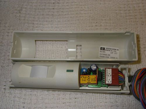
Lot of 4 Bosch DS150i motion detectors
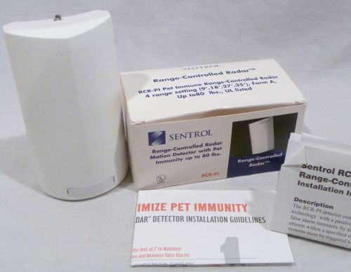
Sentrol RCR-PI Range Controlled Radar Motion Detector Unit w/ Pet Immunity NEW
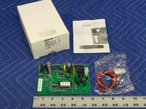
Bosch EA120B Security System Alert Control Unit Board A42
3M - 4 Prong Plugs - CLG-1004-00101D-CER-0C2A
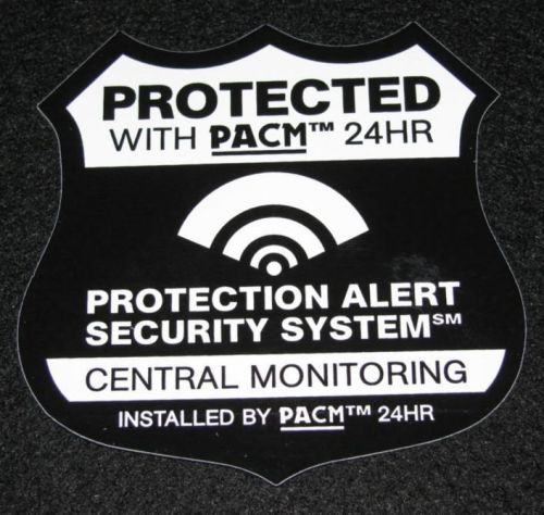
9 Fake Alarm Stickers for Home Security System
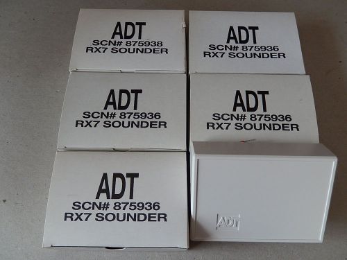
5 ADT RX7 Sounder/Sirens 12Vdc For Alarm Security Systems, NIB
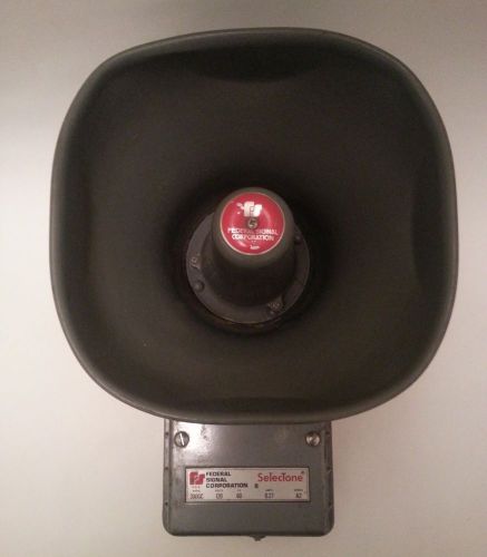
Federal Signal Corporation Selectone 300GC Siren 120V *for parts or repair*
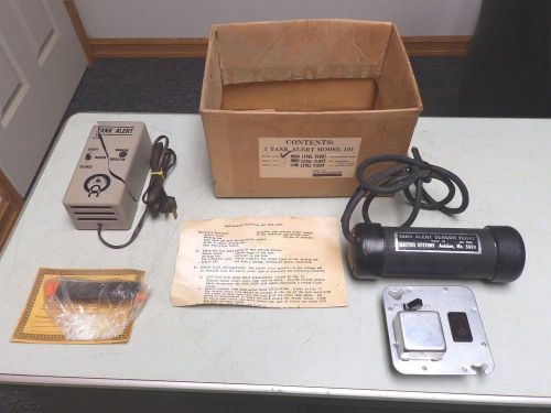
Electro Systems Tank Alert 101 Alarm High Water 101HW FREE SHIPPING
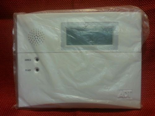
ADT Remote Keypad 6150 ADTLP NEW IN PACKAGING FREE SHIPPING
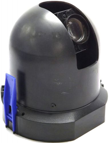
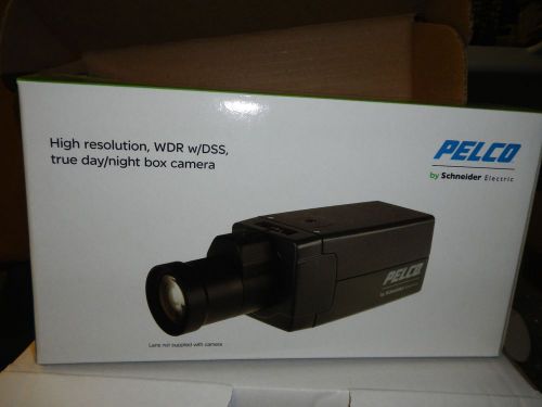
Pelco DD4CBW35 PTZ Camera | 540 TVL | CCD 1/4" | 752 x 582 Pixel | RS-422
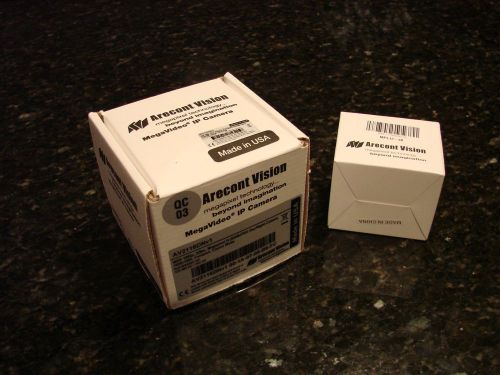
Arecont Vision AV2116DNv1 MegaVideo HD 1080p Day / Night WDR Camera
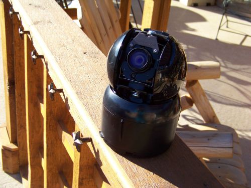
AMERICAN DYNAMICS SPEEDDOME DAY\NIGHT CAMERA RAS917-LSE
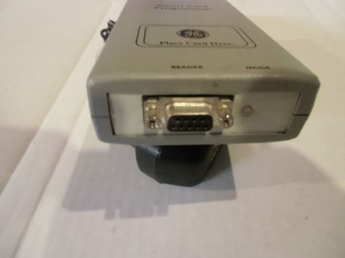
GE Infographics AL1623 card programmer. (AL-1623). Used
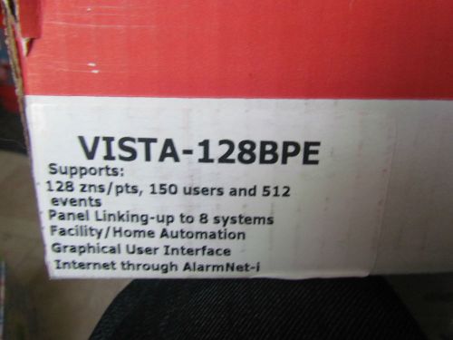
HONEYWELL Vista 128BPE Alarm CONTROL Panel Commercial V128BPE NIB
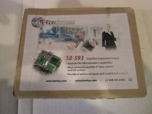
Keri Access Control SB593 board. New in box.
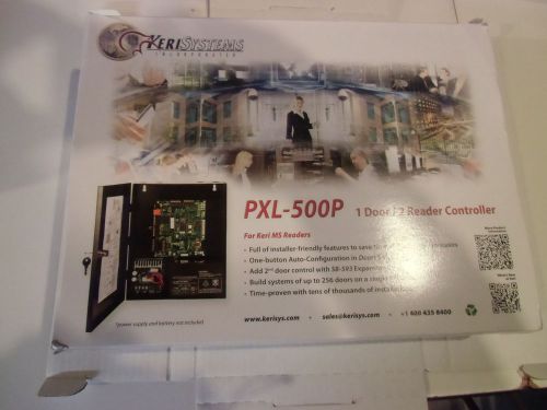
Keri Access Control PXL500P, 12vdc Power Supply,Doors 32 software cd. New in box
By clicking "Accept All Cookies", you agree to the storing of cookies on your device to enhance site navigation, analyze site usage, and assist in our marketing efforts.
Accept All Cookies