US $49.00
Directions
Similar products from Instruction Manuals for Metal Cutting
Tru-Trace Application Photos-Special Milling Applications Catalog
Tru-Trace Application Photos-3D/Man-Au-Trace + Synchro-Trace Catalog
Tru-Trace Application Photos-Synchro-Trace Milling Catalog
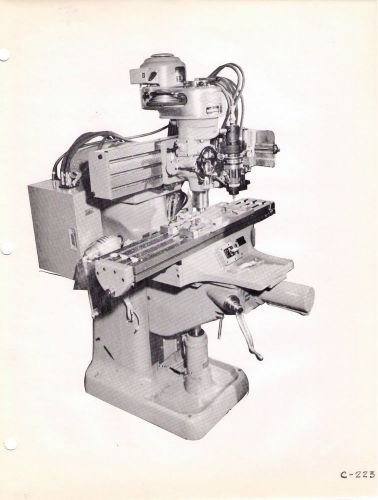
Tru-Trace Application Photos-Man-Au-Trace Milling catalog
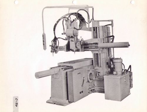
Tru-Trace Application Photos-360 & 3D milling Catalog

Atlas 10" Lathe 10-F series Part List and Service Bulletins
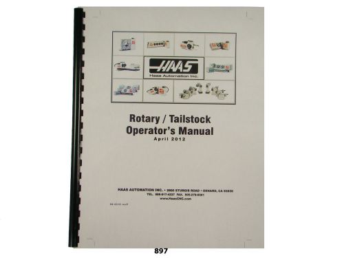
Haas Rotary Tailstock Operators Manual and Parts List *897
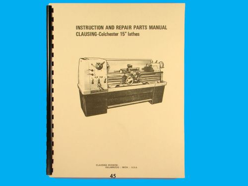
Clausing Colchester 15" Lathe Instruction & Repair Parts List Manual *45
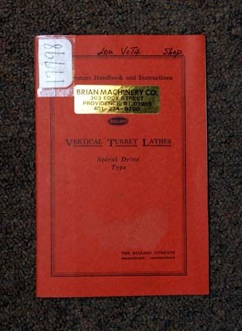
Bullard Operators Manual Vertical Turret Lathe (18000)
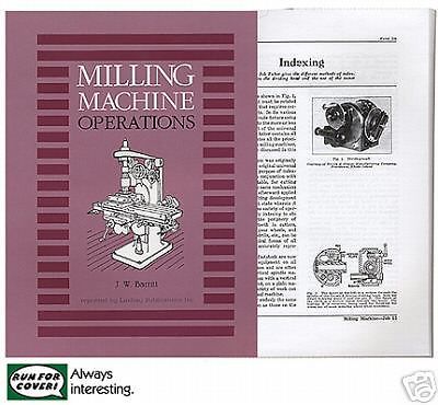
Milling Machine Operations: metalwork shop (Lindsay how to book)

Tricks & Secrets of Old Time Machinists 3: Lathe work hints (Lindsay howto book)

The Founding of Metals: Melting Iron and Making Alloys (Lindsay how to book)
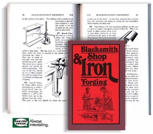
Blacksmith Shop and Iron Forging (Lindsay Lost Technology book)
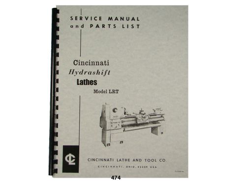
Cincinnati LRT Hydrashift Lathe Service Manual & Parts List *474
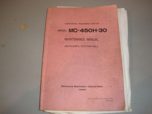
Maintenance Manual For Matssur MC-450H-30 MX3 System
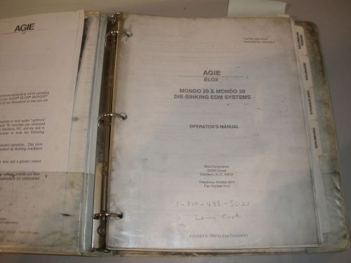
Agie/Elox Mondo 20/30 EDM Sinker Operators Manual
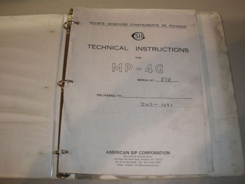
Sip Jig Bore MP-4G Manual Technical Instruction
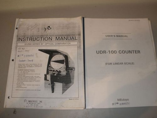
ST22-2500 Optical Comparator 30” Instruction Manual
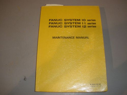
Fanuc System 10/11/12 Control Maintenance Manual

Nomura Swiss CNC Lathe Programing Manual Meldas 320 LV Control
People who viewed this item also vieved
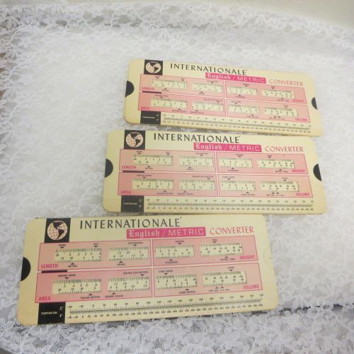
Internationale English Metric Converter Advertising Lot 3 F. Jos. Lamb Co.

MAKE BUILD CREATE YOUR OWN BACKYARD METAL FOUNDRY - DIY - PLANS ON CD!- show original title
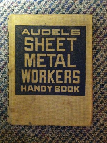
Audels Sheet Metal Workers Handy Book
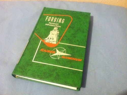
Kaiser Aluminum Forging Product Information
Sheet and Plate Product Information Kaiser Aluminum 1958 2nd Edition
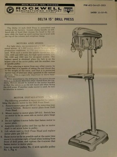
1960-61 Rockwell Delta 15" Inch Drill Press Manual
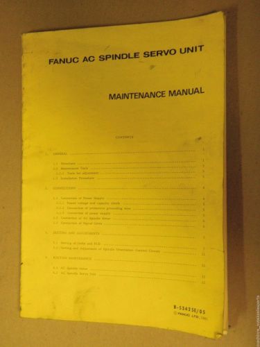
Fanuc AC SPINDLE Operators Manual B-53424E/05_B53424E05_MODEL 3_6_8_12_18_22
LaBlond 24" Tape Turn Regal Lathe Preperation and Maintance Manual
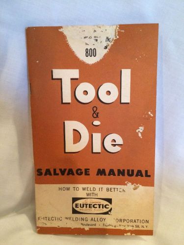
Vintage Eutectic Welding - Weld Salvage of Tools & Dies Booklet Alloy 1952
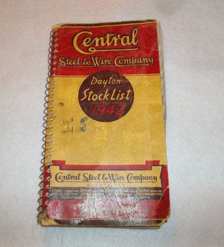
Central Steel & Wire Company Dayton stock list 1942 book vintage collectible
By clicking "Accept All Cookies", you agree to the storing of cookies on your device to enhance site navigation, analyze site usage, and assist in our marketing efforts.
Accept All Cookies