US $65.99
| “NOS” |
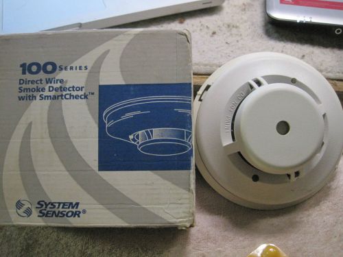
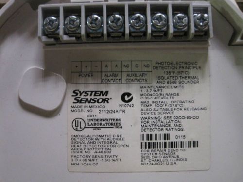
| Brand | SYSTEM SENSOR |
| Type | DIRECT CONNECT SMOKE DETECTOR W/AUDIBLE |
| Model | DIRECT WIRE 100 SERIES SMOKE W/SMARTCHECK |
| Country/Region of Manufacture | Mexico |
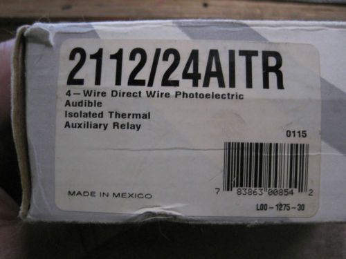
| MPN | 2112/24AITR |
| UPC | 783863008542 |
Directions
Similar products from Other Alert Systems & Accessories

L-1 Identity Solutions Fingerprint Scanners
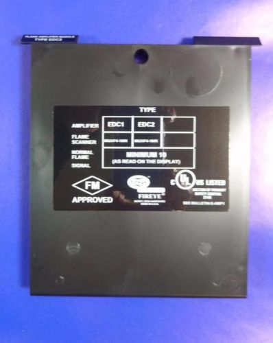
FIREYE Type EDC2 Direct Coupled Input Flame Amplifier Module
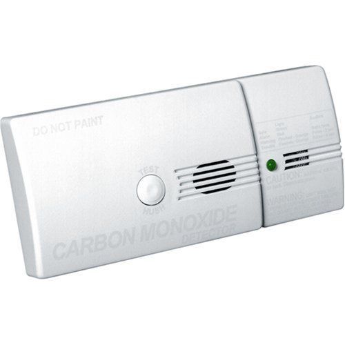
ESL SAFEAIR CARBON MONOXIDE ALARM NEW IN BOX ES-240-COE
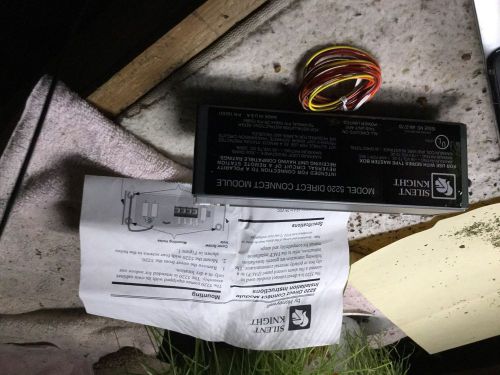
SILENT KNIGHT 5220 DIRECT CONNECT MODULE
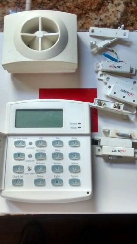
GE Interlogix Concord Express Control Panel With Accessories 60-806-95R Ademco
STI Safety Fire Alarm Cover, Stopper II W/O Horn, W/Spacer. STI-1230. **NEW**
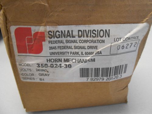
FEDERAL SIGNAL CORPORTATION HORN MECHANISM 350-024-30 24 VOLT GRAY
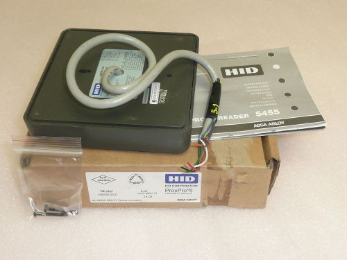
HID CORP. PROXPRO II PROXIMITY READER (GRAY) - NO KEYPAD PIGTAIL

Ademco Vista-20P,15P Installation and Setup Guide
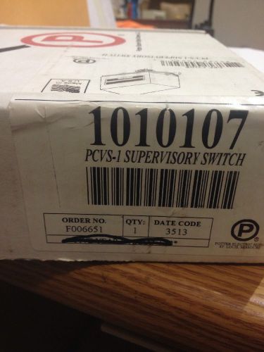
POTTER PCVS-1 VALVE SUPERVISORY SWITCH, SINGLE CONTROL

HID 1326 ProxCard II Card AMAG Prox 37 Bit Format: S10401 SETEC- Pack of 100
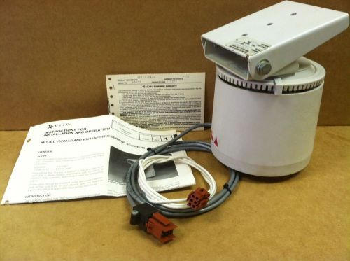
Vicon V3200-24AP Indoor Scanner - Microscan™
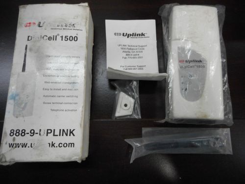
NEW UPLINK DIGICELL 12V 1500 DIGI CELL CELLULAR COMMUNICATOR ALARM BACKUP RADIO

Resonating Horn #55-120-1 120VAC Gray NEW (B6)
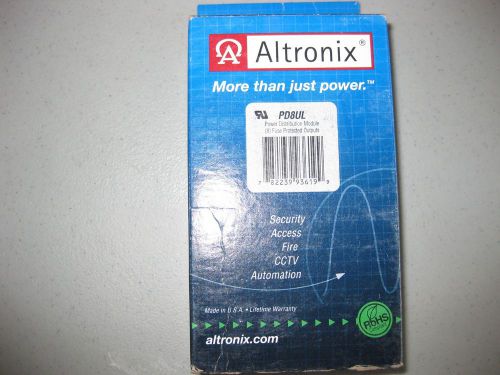
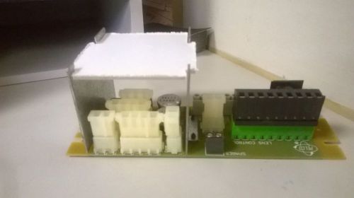
Altronix PD8 power distribution board. New in box.

GE Security 1840-N Rare Earth Magnet For Steel Or Aluminum Doors
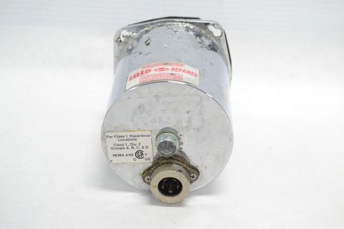
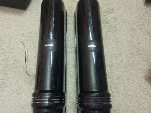
IRIS OPTICAL LASER VIDEO CAMERA ENCLOSURE MODULE SAFETY AND SECURITY B276129

Javelin Rapid Eye Remote Multiplexer JRRP4P16 32 Inputs 8 Outputs New Old Stock

VISTA VM1200DB Maglock with bond sensor
People who viewed this item also vieved
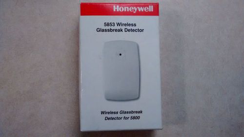
2 Ademco/Honeywell 5853 Wireless Glassbreak Detectors, NEW!!!!
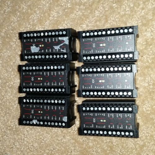
LOT OF "6" INTELLI-M S-IDC-1020 INTEGRATED DOOR CONTROLLER

3M PFIM27V2 - Display privacy filter - 27" wide - black - for Apple iMa PFIM27V2
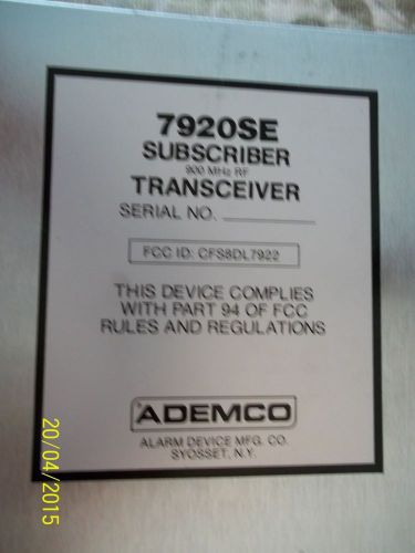
Ademco 7920SE Subscriber Transceiver
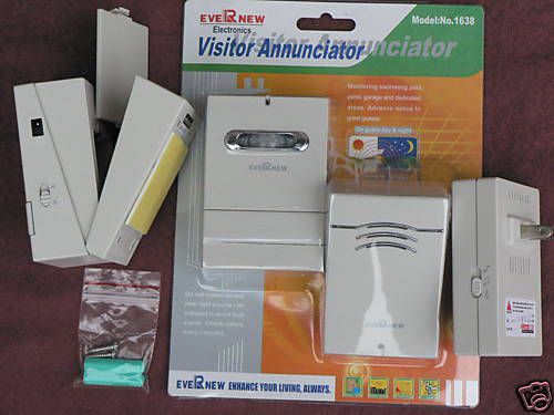
NW EASY 2 INSTALL WIRELESS MOTION SENSOR-REDUCED PRICE (2 UNITS)

NIB Bosch ds1102i glass break detector
Optex AX Wonderex Photoelectric Detector AX-250Plus Receiver and Transmitter

Occupancy Sensor, Leviton, ODS0D-IDI, NEW, FREE SHIPPING, %4F%
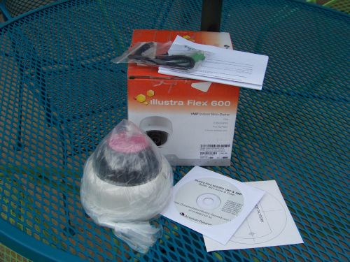
AD Illustra Flex 600 ADCI600F-D111 1MP D/N IR Indoor IP Minidome w/ 3-9mm Lens
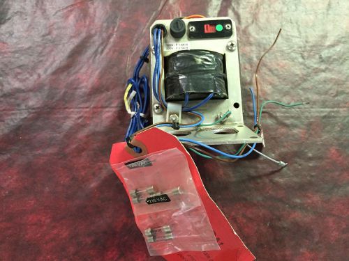
PELCO TRANSFORMER - #0503 - NEW
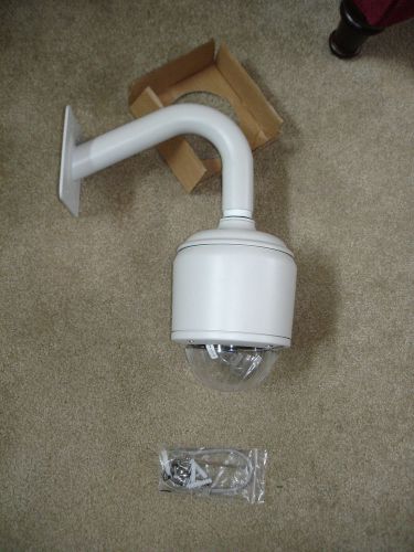
Security Camera outdoor Housing SENTRY 360 Camera FS-DM-DOME-HB
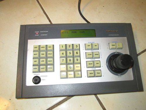
V2116 Infinova System Keyboard Keypad With Joystick for Surveillance System
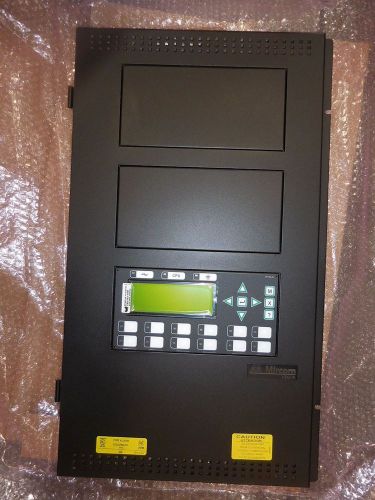
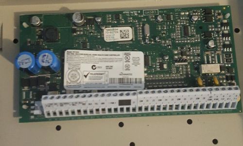
Mircom FX-2003-12NDS Network Fire Alarm Control Panel Chasis New

Honeywell Ademco 6139 Home Security Alarm Alpha Console Keypad Warning Systems

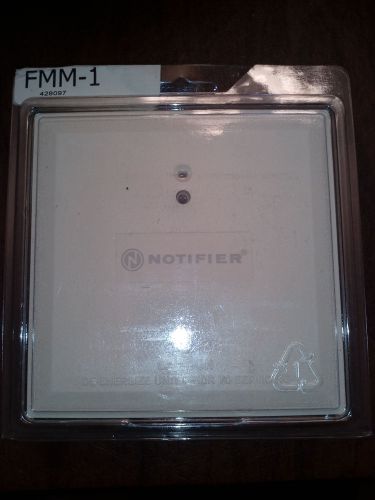
Notifier By Honeywell FMM-1 Fire Alarm Monitor Module
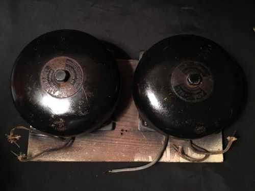
Vintage Old Edwards Adaptabel Bell 12 Volt Gas Fire Station Alarm Loft Decor (2)
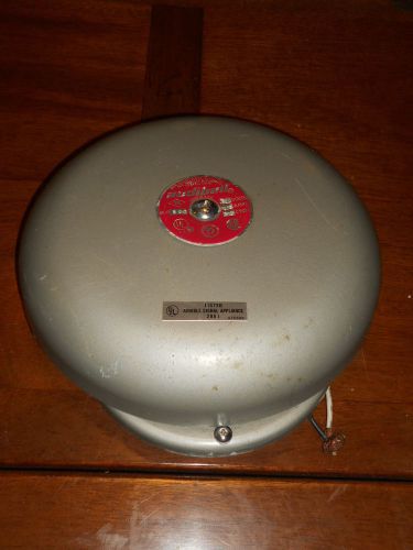
Vtg Thomas Industries Audibell 10" No KB 501 Alarm Bell 120V 05 amps 60 cycle

System Sensor DST1.5 Duct Smoke Detector Sampling Tube New Unused Slightly Rusty
By clicking "Accept All Cookies", you agree to the storing of cookies on your device to enhance site navigation, analyze site usage, and assist in our marketing efforts.
Accept All Cookies