


US $600.00
| Condition | Seller refurbished
:
An item that has been restored to working order by the eBay seller or a third party not approved by the manufacturer. This means the item has been inspected, cleaned, and repaired to full working order and is in excellent condition. This item may or may not be in original packaging. See the seller’s listing for full details.
|
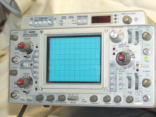
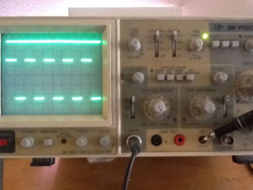
| Seller Notes | “This is a complete Oscillosocpe package, just like the original package from Tektronix” |
Directions
Similar products from Portable & Digital Oscilloscopes
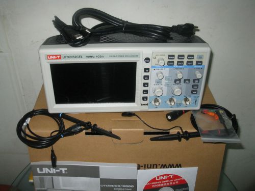
Digital 50MHz Oscilloscope Scopemeter 2Channel 1GS/s 7" Color LCD USB UTD2052CEL
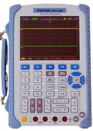
Handheld Oscilloscope Scopemeter 200MHZ 500MS/s 2Channels Multimeter USB DSO1200
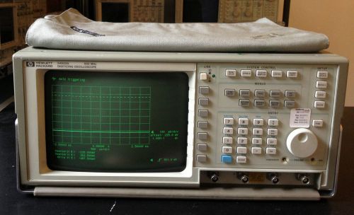
HP/ Agilent 54503A 500MHz Digitizing Oscilloscope w/ 4 Channels, Tested
2 Channel PC Computer Digital Storage USB Oscilloscope 5V 8kHz
Sony/Tektronix Type 305 DMM Oscilloscope High Voltage Module
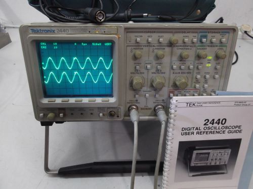
TEKTRONIX 2440 500MHz OSCILLOSCOPE, WORKING. AS IS, READ!
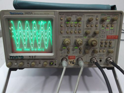
TEKTRONIX 2465A 350MHZ OSCILLOSCOPE 4 CH GOOD
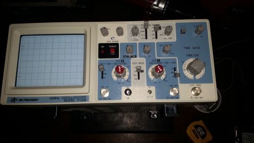
BK Precision 2120B Analog Oscilloscope w/ Probes and Power cable
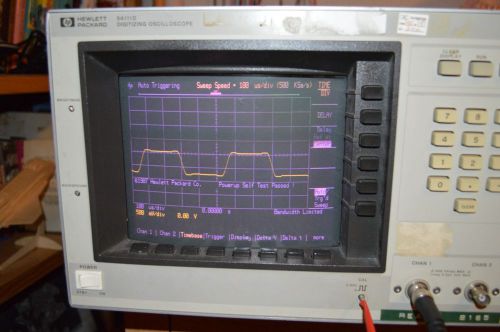
HP 54111D Digitizing Oscilloscope
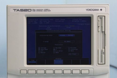
YOKOGAWA TA520 / 704310 TIME INTERVAL ANALYZER-SUFFIX -1-M
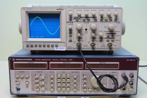
METRIX OX 8050 100MS/s 60MHZ DIGITAL/ANALOG OSCILLOSCOPE(#M-5003 / N140854YEH )
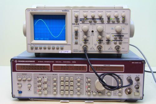
METRIX OX 8050 100MS/s 60MHZ DIGITAL/ANALOG OSCILLOSCOPE(#M-5004 / N140851YEH )
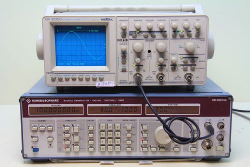
METRIX OX 8050 100MS/s 60MHZ DIGITAL/ANALOG OSCILLOSCOPE(#M-5005 / N142392YEH )
BK Precision 2160 60 MHz Oscilloscope !!!!!PRE FIRE SALE!!!!!
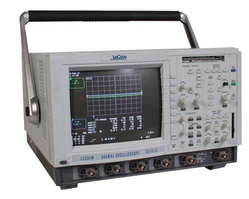
LeCroy LC334M 500 MHz Oscilloscope single 2 GS/s 2 Mpt, Quad 500 MS/s 500 KPT
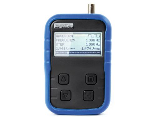
Velleman HPG1 1Mhz Pocket Function Generator
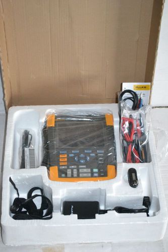
New Fluke 190-062 190 Series II 60 MHz, 625 MS/s 2 Ch Color ScopeMeter
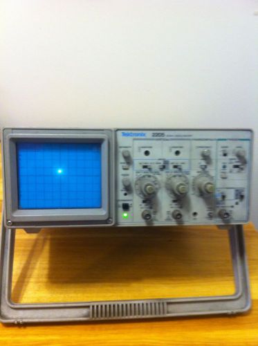
TEKTRONIX 2205, 20 MHZ OSCILLOSCOPE
People who viewed this item also vieved
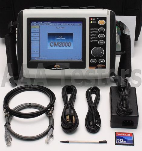
Sunrise Telecom CM2000 DOCSIS 2.0 Cable Modem Network Analyzer CM-2000
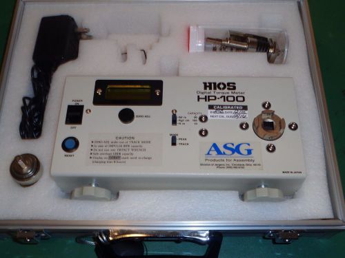
HIOS/ASG HP-100 DIGITAL TORQUE TESTER. *CALIBRATED*
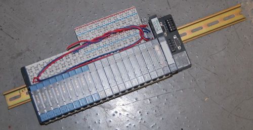
Moeller XI/ON Din Rail w/Modules, Software, Cable §
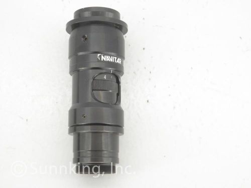
Navitar Machine Vision 1-6265 6.5X Zoom Lens
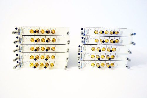
Lot of 10 National Instruments NI 5540 250MHz-6GHz RF
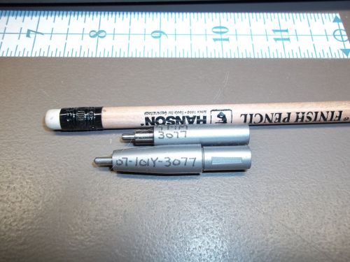
KEYSTONE ELECTRONICS 3077 Top/Bottom eyelet tool; TOOL STAKING FOR EYELETS
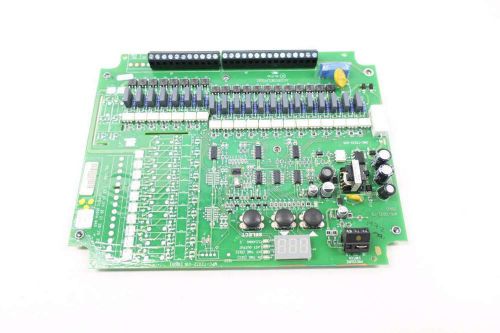
AMETEK MPC-T2032-016 OUTPUT PULSE TIMER PCB CIRCUIT BOARD D530252
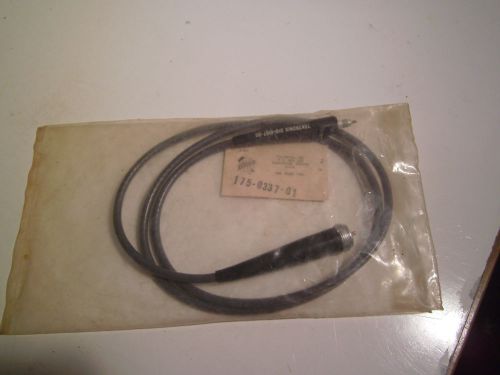
Vintage NOS Tektronix 175-0337-01 Cable/Cable labeled 010-0187-00
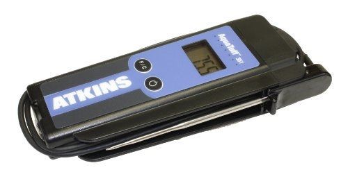
Cooper-Atkins 35132 Series 351 AquaTuff Wrap and Stow Waterproof Thermocouple
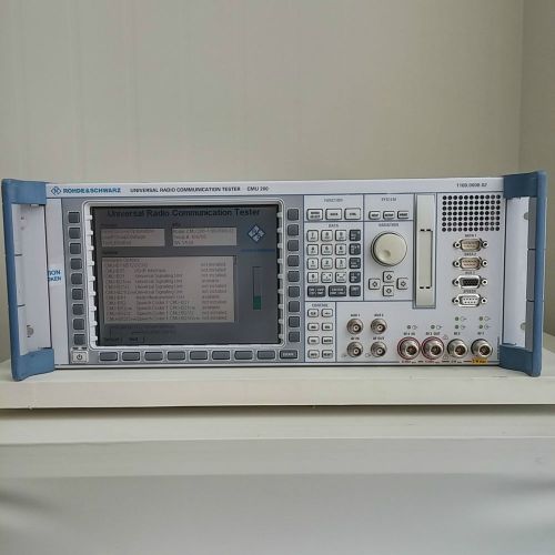
Used R&S Universal Radio Communication Tester CMU200 FMR6/Intel Celeron/256MB
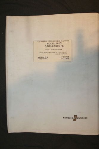
HP 182C OSCILLOSCOPE OPERATING AND SERVICE MANUAL
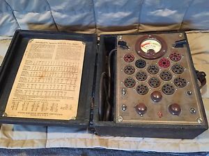
Antique Weston Electronic Tube Tester Meter vintage radio tester old part tube
Bacharach 0019-3265 Water Trap/Filter Assembly for Probe Hose Assembly
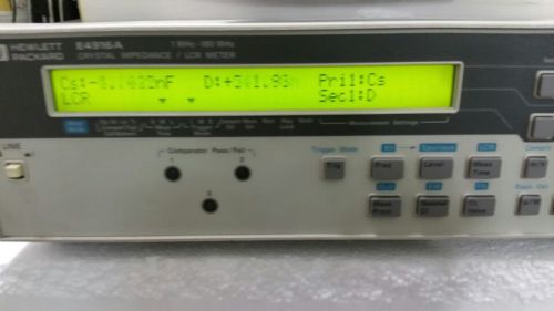
Agilent HP E4916A Crystal Impedance Meter (No Option)
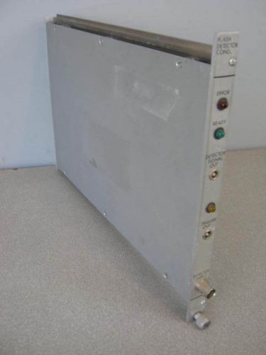
SEC Flash Detector Cond. WW-007 CAMAC Crate Module
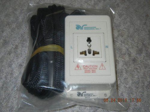
Associated Research Hipot Receptacle Adapter Box, Part Number: 36544, NEW
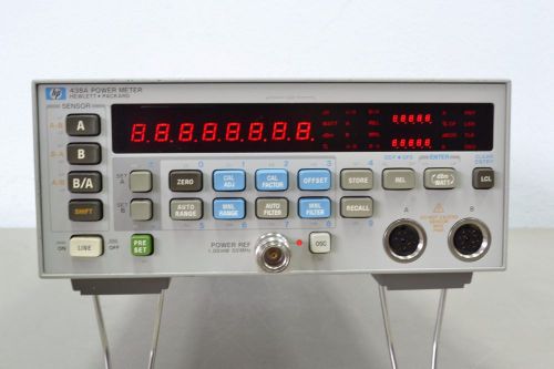
HP Agilent 438A Dual Channel Digital Power Meter w/opt 700
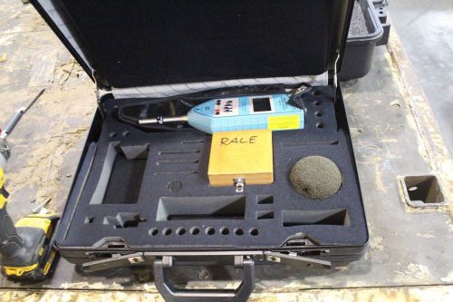
CEL-INSTRUMENTS OCTAVE BAND SOUND LEVEL METER CEL-266
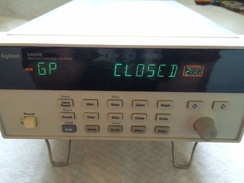
Agilent Control Switch Mainframe 3499B and DC-18GHz Microwave Switch 44476A
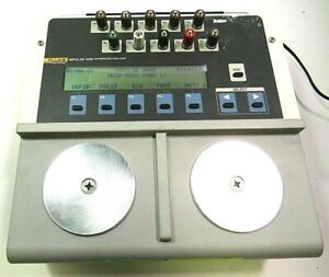
Fluke Biomedical Impulse 4000 ECG DEFIB /PACER Analyzer-Free Shipping-
By clicking "Accept All Cookies", you agree to the storing of cookies on your device to enhance site navigation, analyze site usage, and assist in our marketing efforts.
Accept All Cookies