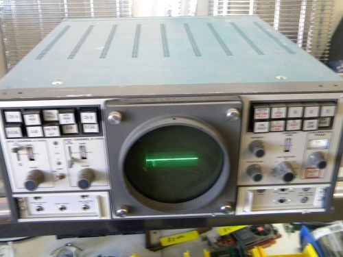
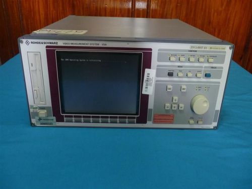
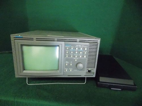
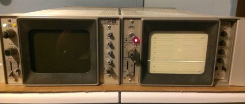
Tektronix 520A NTSC Vectorscope: The Tektronix 520A NTSC Vectorscope is designed to measure luminance, hue and saturation of the NTSC1 color television signal. Solid-state circuitry is used to reduce power consumption and heat dissipation. With less heat generated, no fan is required and quieter operation is achieved. The 520A is intended for continuous monitoring of the signal. Self-cancelling pushbutton switches permit rapid selection of television signal characteristics, and checking of vectorscope calibration. The 520A decodes color signals to recover chrominance and luminance information. Luminance signal can be viewed in the Y mode or reapplied to the demodulated chrominance signal to view R, G, B, I, or Q. One line of sweep, differential gain and differential phase can be displayed by push-button selection. I National Television System Committee Vector display is a polar plot, where the length of the vectors is a function of the peak-to-peak amplitude of the chrominance signal. Angular displacement is relative to the phase of the reference vector, referred to as burst. The 520A is equipped with two signal inputs that can be operated independently or time shared. The chrominance and luminance gain accuracy of each channel can be checked using the internal test signal. A digital line selector is used to select a single line of Vertical Interval Test Signal (VITS), from line 15 to line 21 of either field. In addition, one line can be selected for presentation on both fields, for Vertical Interval Reference (V IR) signal display. CHARACTERISTICS Electrical specifications for this instrument are valid over the specified environmental limits, found at the end of this characteristics section. Calibration within an ambient temperature range of +20°C to +30°C is required. A 20 minute warmup period is required for stated accuracies. TABLE 1-1 Color Processing Characteristic Performance Requirement CHROMINANCE Subcarrier Frequency (F se ) 3.579545 MHz. Fse Bandwidth Fse +500 kHz ±1Q0 kHz to Fse -500 kHz ±100 kHz. Vector Phase Accuracy 1° or less error, marker to graticule. Incremental Accuracy 0.5° error or less in any 10° graticule segment. Quadrature Phase +2° to -2°. Adjustment Range Test Circle Amplitude 0.707 V ±1%. ® Characteristic Performance Requirement Color Decoding Accuracy R, G, or B ±3% of color component amplitude. I Axis 57° ±2° from burst. Q Axis 147° ±2° from burst. Differential Gain2 Deflection Factor 5% deflects trace 25 IRE units (5% or 0.5 inches) ±5%. VITEAC, modulated staircase signal (chrominance +3 dB, -6 dB of 143 mV). Accuracy (50% APL) ± 1% last 90% of trace. Dynamic Gain ± 1% last 90% of trace. (10% to 90% APL) Differential Phase3 0.1° deflects trace at least 1 Resolution IRE unit (0.1 inch). VITEAC, modulated staircase signal (chrominance +3 dB, -6 dB of 143 mV). 2The change in gain of the color subcarrier as the luminance level is varied. 3The change in phase of the color subcarrier as the luminance level is varied. 1-1 User Information-520A TABLE 1-1 (cont) Characteristic Performance Requirement Differential Phase Burst Phase Reference 0.3° of differenti al phase (50% APl) last 80% of trace. Dynamic Phase 0.3° of differential phase (10% to 90% APL) last 80% of trace. External Phase Reference 0.15° of differential phase (50% APLI last 90% of trace. Dynamic Phase 0.15° of differential phase (10% to 90% APL) last 90% of trace. Calibrated Phase Range +15° to - 15°. Accuracy 10% or less 2° increment. (Total incremental error ±0.5° between +14° and _14°. Phase Reference Burst Subcarrier Regeneration 1° with input burst frePhase Error quency of 3.579545 MHz ±10 Hz. Phase Error With 1° per 10°C, maximum of Temperature 5° over ambient operating range. Phase Error With Input 1° for signal variation of Signal Variation ±3 dB from 1 V composite video. 3° for variation of burst/ sync ratio of -6dB to +10 dB. Phase Error Due To 0.2° for burst timing errors, Breezeway Stability including burst width variance (8-11 cycles) and breezeway variance (±280 ns). Phase Error Due 1° with rms white noise at To Noise -24 dB (0 dB = 700 mV rms). External 3.579545 MHz 1.5 V to 2.5 V. cw Input Range LUMINANCE Luminance Bandwidth 700 kHz to 1.1 MHz. luminance Gain 140 IRE units/volt, ±1%, in 75% Cal. Luminance Gain Range 0.7: 1 to 1.4: 1 (+3 dB to -3 dB). '-2 TABLE 1-2 Input Signal Processing Characteristic Performance Requirement Video Input Amplitude 0.7 V to 1.4 V (sync tip to Range peak white). Maximum DC level ±20 V. Gain Stability Time ±1%. Temperature ±5%. Line Voltage ±1%. Time Sharing Switching 1/4 H rate, locked to H Rate sync. Horizontal Sync Input Range (50% APL) 0.7Vto1.4V. Dynamic (10% to 90% APL) 0.8 V to 1.4 V. External Horizontal Sync Input Range (50% APl, 0.7Vto1.4V. Composite Video) Dynamic (10% to 90% APL, 0.7 V to 1.4 V. Composite Video) Composite Sync 3.5 V to 7.5 V. Gain Range, Variable 0.5:1 to 1.4: 1 (+3 dB to (Channel A and B) -6 dB). Input Attenuator 100% Vectors 0.75 gain ±2% (75% Cal). 75% 140 IRE units/volt ±1%. Maximum Gain Internally adjustable to at least 5 times gain (75% Cal). Return loss (input in use or not, power on or off). Input A and B At least 40 dB, dc to 5 MHz. External Phase Reference At least 40 dB, at 3.58 MHz. External Sync4 At least 46 dB, dc to 5 MHz (connected for 3.5 to 7.5 V). At least 40 dB, dc to 5 MHz (con nected for 0.7 to I 1.4 V). 4Normally connected for 3.5 V to 7.5 V amplitude at the factory. ® TABLE 1-3 Horizontal and Vertical Display Characteristic Performance Requirement Clamp Stability Temperature ±1 minor division. Line Voltage ±1 minor division. ~. -- Vector Stability, With ±2 minor divisions X and Y Rotation of A and B axis (±2 mV of Fsc on sync Phase Controls tips) . Luminance, Display Shift ±1 minor division (with dynamic shift of APL from 10% to 90%). . - Display Shift Between ±3 IRE units. Line Sweep, I, Q, and Differential Phase. TABLE 1-4 Power Source Characteristics Performance Requirement Line Voltage Ranges 90-110 Vac 104-126Vac 112-136 Vac 180-220 Vac 208-252 Vac 224-272 Vac Maximum Power 100 W. Consumption (115 Vac at 60 Hz) Maximum Current 1.1 A. (115 Vac at 60 Hz) Line Frequency 47-63 Hz. Power Cord Conductor Identification Conductor Color Alternate Color Ungrounded (Line) Brown Black Grounded (Neutral) Blue White Grounding (Earthing) Green-Yellow Green-Yellow REV. C, JUN. 1977 User Information-520A CRT The 520A NTSC Vectorscope uses a T5201 crt having a minimum horizontal resolution of 12 lines/em, and minimum vertical resolution of 10 lines/em. Maximum geometry (bowing) error is 0.5 mm; orthogonality variation is 1° or less. The useable scan radius is 5.5 em. The trace rotation is at least +3° to -3°, and is controlled by the front panel BEAM ROTATION control. ENVIRONMENTAL CONSIDERATIONS Storage or transportation (non-operating) temperatures of -40°C to +65°C and altitude variations up to 50,000 feet are acceptable. Following a 20 minute warmup period, the performance requirements of this instrument are met in a temperature range of O°C to +50°C at altitudes up to 15,000 feet. In the original packaging, or when repackaged according to instructions, this instrument is qualified under National Safe Transit Committee procedure 1A, Catagory 1. See repackaging instructions located at the rear of the Disassembly Instructions section of this manual. PHYSICAL SIZE The 520A NTSC Vectorscope is normally shipped in a rackmounting configuration. The following dimensions are for the rackmount. Bench mount dimensions can be found in the Mounting Hardware pull-out. Height 7 inches (17.8 em), width 19 inches (48.3 cm), depth 19.75 inches (50.2 em). Net weight is 33 pounds (15 kg); shipping weights are approximately 61 pounds (27.7 kg) domestic and 82 pounds (37.3 kg) export. 1 This unit in in excellent used condition and is shipped with only what is in the pictures that is the unit itself and the power cord. It is the exact device you will receive. It came from a working environment and has been tested for power on and function keys. The device will be packaged carefully and shipped to you expeditiously. If there are any questions or concerns anywhere in the process contact me immediately and they will be addressed promptly to your satisfaction. I offer FREE economy shipping and a 30 day return policy. Ships to the lower 48 United States only. Please check out my other items: -------------> lynfra8
By clicking "Accept All Cookies", you agree to the storing of cookies on your device to enhance site navigation, analyze site usage, and assist in our marketing efforts.