
US $410
Directions
Similar products from Plug-In Modules
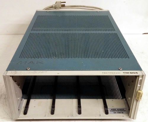
TEKTRONIX TM504 OPT. 02 MAINFRAME CHASSIS
HP Agilent 08350-60022 Circuit Board / Card Assembly
HP Agilent 08350-60061 Circuit Board Assembly
HP Agilent 08350-60093 Circuit Board
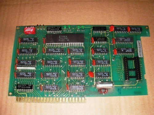
HP AGILENT 8350B SWEEP OSCILLATOR CIRCUIT BOARD P/N HP 08350-60067
HP Circuit Board A-2215-45 _ 08350-60053 _ 24003F
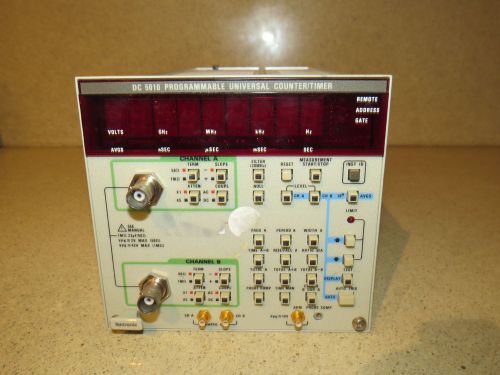
TEKTRONIX DC5010 DC 5010 PROGRAMMABLE UNIVERSAL COUNTER/TIMER PLUG IN (PI1)
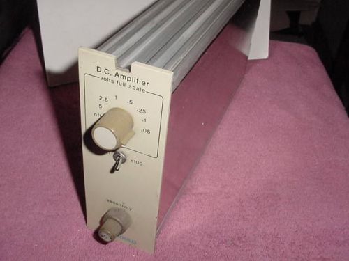
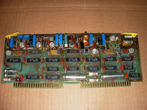
**NICE** GOULD 13-4615-00 DC AMPLIFIER PLUG IN MODULE **FREE SHIPP USA**
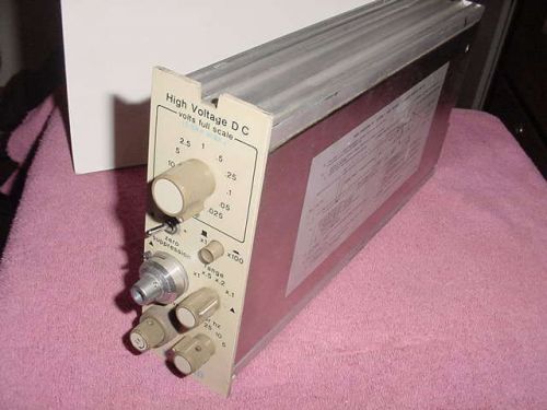
**NICE** GOULD 13-4615-90 HIGH VOLTAGE DC AMPLIFIER 293190D **FREE SHIPP USA**
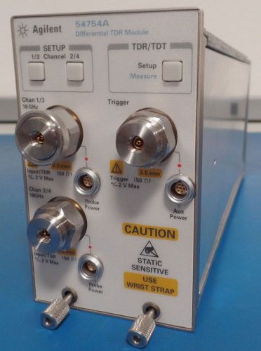
HP/Agilent 54754A Differential & Single-ended TDR/TDT Module
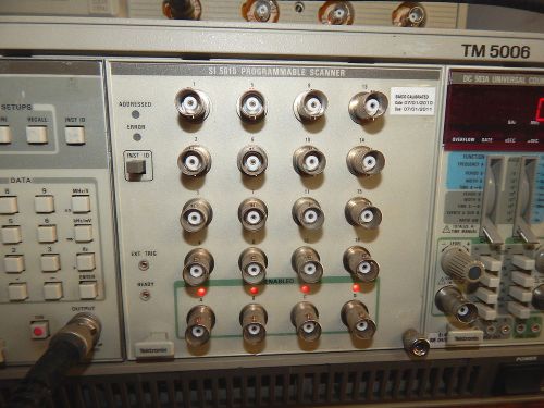
Tektronix SI 5010 Programmable Scanner Plug-In
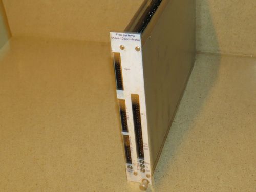
PICO SYSTEMS SHAPER / DISCRIMINATOR CAMAC MODULE PLUG IN (SH1)
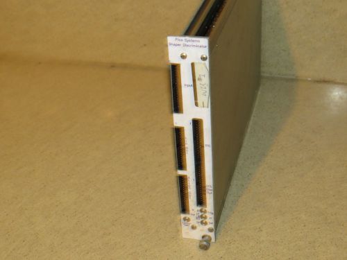
PICO SYSTEMS SHAPER / DISCRIMINATOR CAMAC MODULE PLUG IN (SH2)
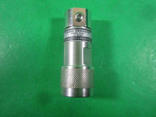
HP Hewlett Packard Coaxial Termination 50 ohms -- 908A -- Used
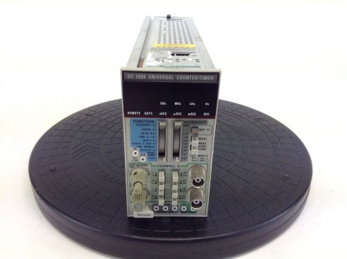
Tektronix DC 5009 Universal Counter / Timer Plug-In Module
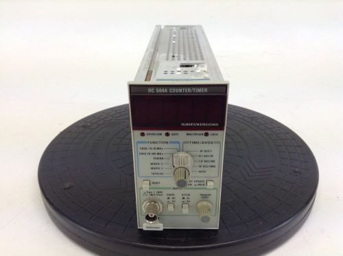
Tektronix DC 504A Counter/Timer
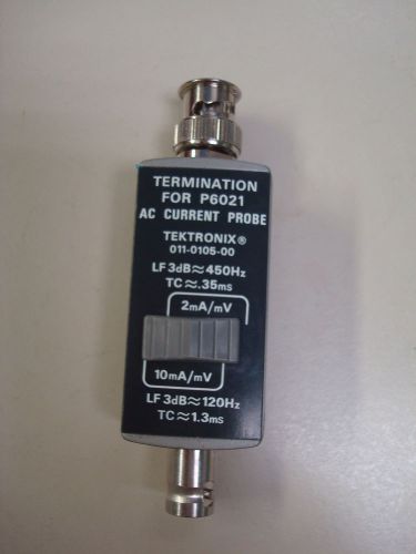
Tektronix 011-0105-00 Termination Coaxial for P6021 AC Current Probe
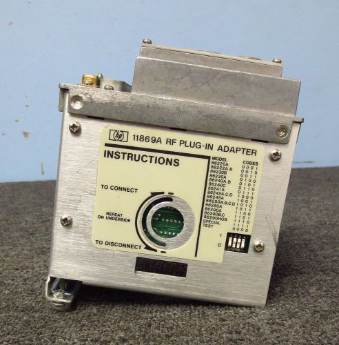
HP / Agilent 11869A RF Plug In Adapter for 862XX Series Plug Ins
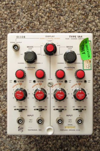
TEKTRONIX TYPE 1A4, FOUR CHANNEL AMPLIFIER PLUG-IN. PULLED FROM WORKING 'SCOPE
People who viewed this item also vieved
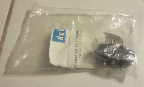
Tektronix Curve Tracer TO-3 C Sense Transistor Adapter 013-0100-01
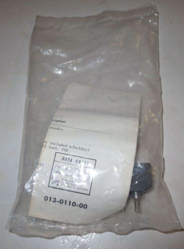
Tektronix Curve Tracer Stud Diode (DO-4, DO-5) Adaptor 013-0110-00
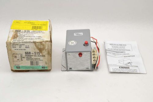
NEW WHITE RODGERS 668-515 OIL BURNER CONTROL 120V-AC 0.4A AMP CONTROLLER B490507
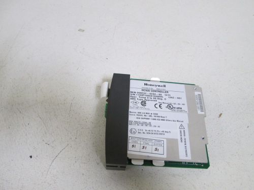
HONEYWELL HC900 CONTROLLER 900C32-0244-00 *NEW OUT OF BOX*
E119932 AWM 2919 80C 30V VW-1 LOW VOLTAGE COMPUTER CABLE IMPACT VELOCITY SERIES
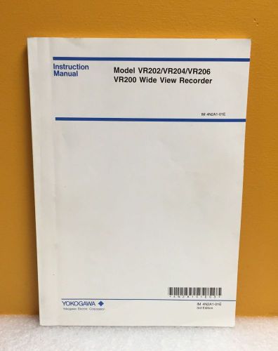
Yokogawa IM 4N2A1-01E VR202/204/206 VR200 Wide View Recorder Instruction Manual
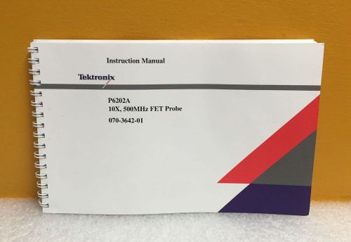
Tektronix 070-3642-01 P6202A 10X, 500 MHz, FET Probe Instruction Manual
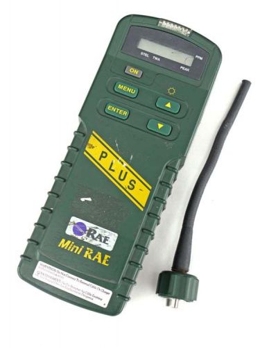
Mini Rae PLUS PGM-76IS Portable Photoionization Gas Detector Sensor Monitor PID
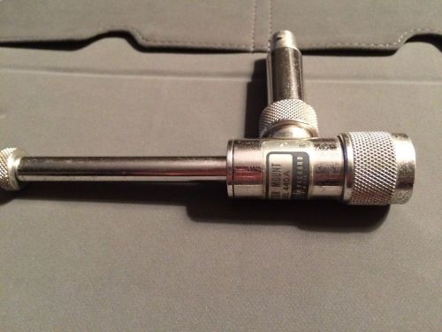
HP / Agilent 440A Crystal Detector Mount - Type-N Male, BNC Female
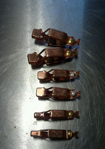
6X NEW Mueller Copper Alligator Automotive Battery Clips USA MADE

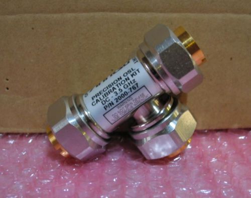
Anritsu 2000-767 3.5GHz 7/16 DIN Male OSL Open Short Load Calibration Kit
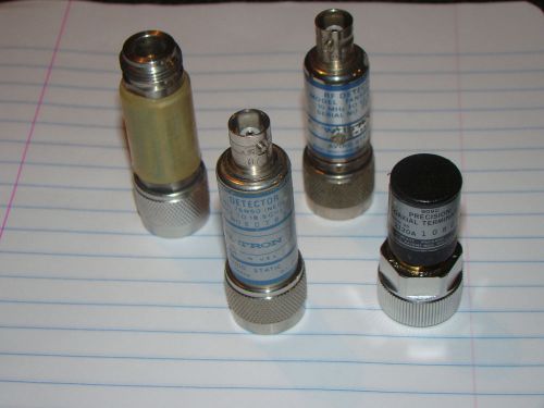
Lot of RF Microwave Test Parts (153)
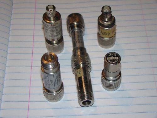
Lot of RF Microwave Test Parts (152)
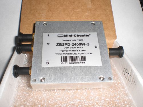
MINI-CIRCUITS POWER SPLITTER 700-2400 MHz - ZB3PD-2400W-S
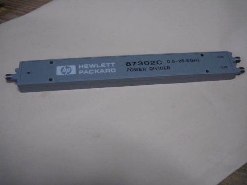
HP87302C 0.5-26.5GHz Power Divider
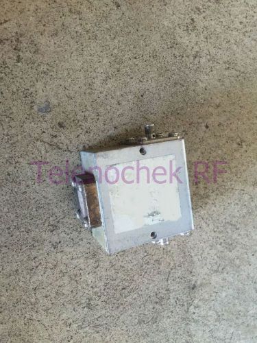
RF microwave single junction isolator 287 MHz - 431 MHz / 150 Watt / data
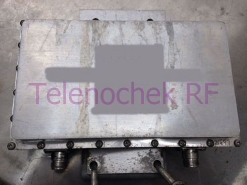
RF WiFi WLAN UNII-3, chan 157 band pass filter 5785 MHz 20 MHz BW, 10 Watt, data
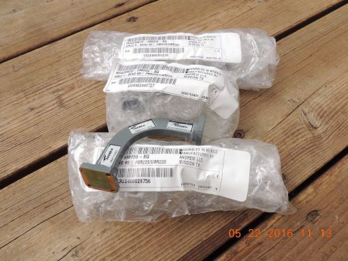
4 ea. NEW Andrew Gold Plated WR42 H bend Waveguide Sections 24GHz
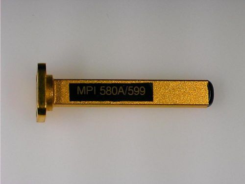
MPI WR-28 Gold over brass Waveguide Termination model 580A/599
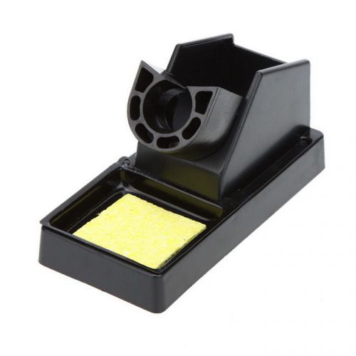
Plastic Soldering Iron Stand Solder Base Welding Wire Holder with Sponge
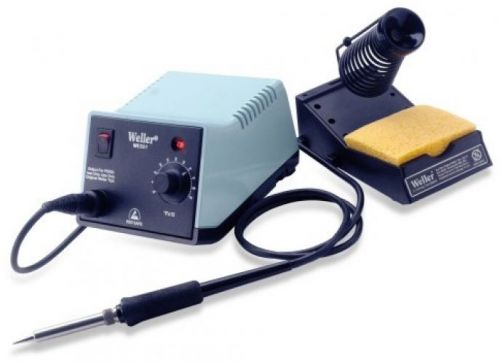
NEW Weller WES51 Analog Soldering Station Power Unit Pencil Stand and Sponge
By clicking "Accept All Cookies", you agree to the storing of cookies on your device to enhance site navigation, analyze site usage, and assist in our marketing efforts.
Accept All Cookies