

US $320.00
| Condition | Used
:
An item that has been used previously. The item may have some signs of cosmetic wear, but is fully operational and functions as intended. This item may be a floor model or store return that has been used. See the seller’s listing for full details and description of any imperfections.
|
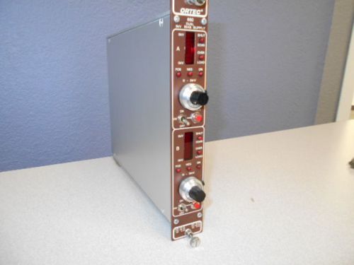
| Seller Notes | “Perfect functional unit. No dings, dents or scratches” |
Directions
Similar products from Plug-In Modules

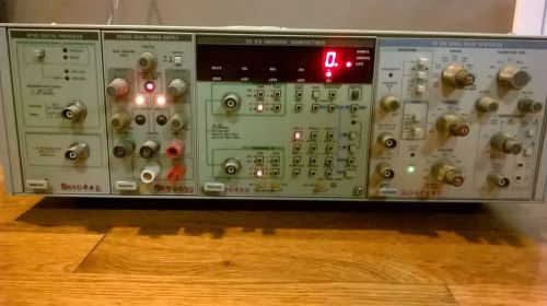
TEKTRONIX TM 506 6 SLOT CHASSIS w/ DP501, PS503A, DC 510, PG 508
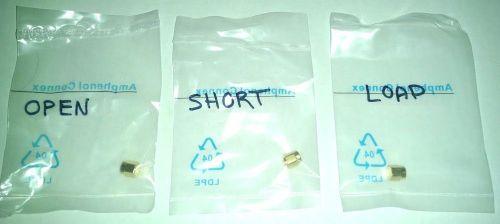
Antenna Analyzer and VNA Open/Short/Load 6GHz SMA Calibration kit
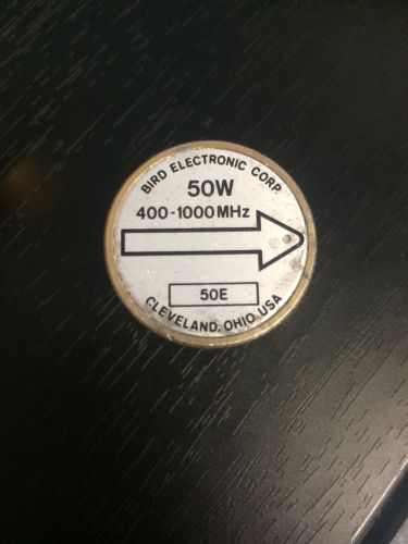
Bird 50E 400-1000 MHz 50 Watts 7/8" Standard Wattmeter Plug-In Element Slug
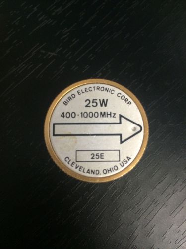
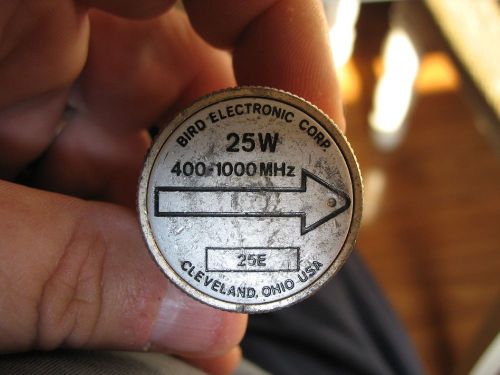
Bird 25E Wattmeter Element Slug 400-1000 MHz 25 Watts
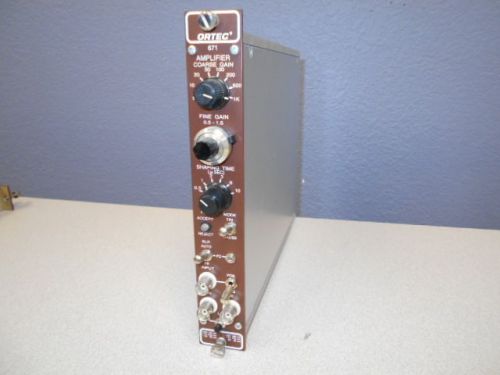
ORTEC Model 671 High-Performance Energy Spectroscopy Amplifier
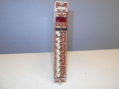
ORTEC Model 850 Quad Single-Channel Analzyer (SCA)
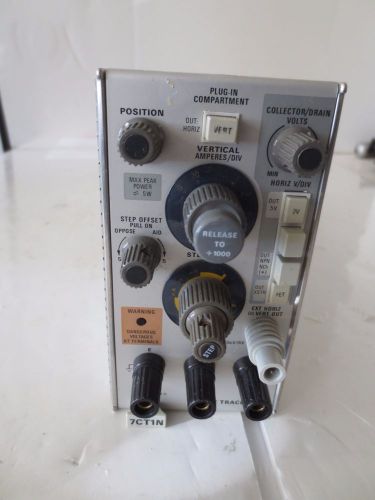
TEKTRONIX 7CT1N CURVE TRACER PLUG IN
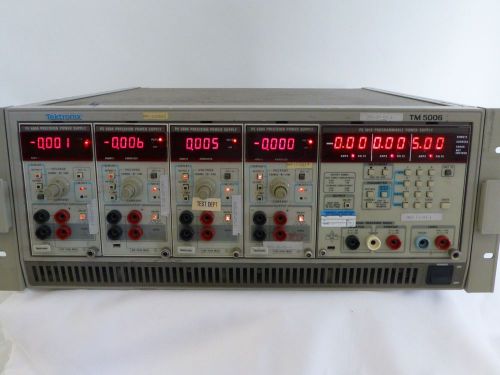
Tektronix TEK TM5006 PS 5010 Programable Power supply x4 PS 5004 Precision power
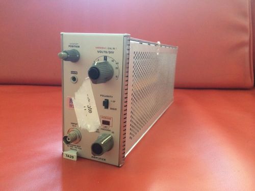
Tektronix 7A29 Amplifier Plug-In Rack Module for 7000 Oscilloscope (1)
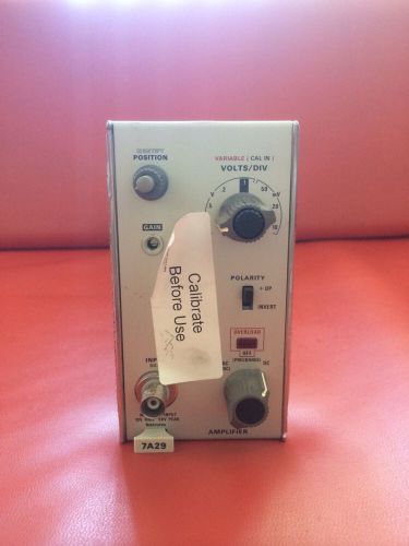
Tektronix 7A29 Amplifier Plug-In Rack Module for 7000 Oscilloscope (2)
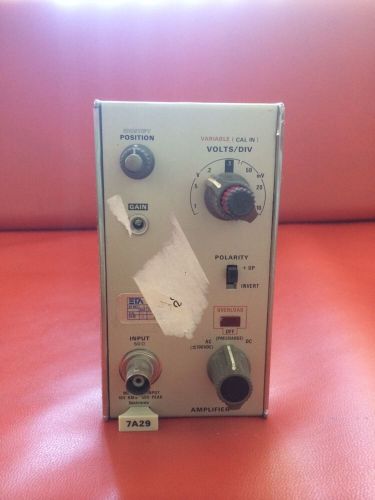
Tektronix 7A29 Amplifier Plug-In Rack Module for 7000 Oscilloscope (3)
tektronix AM503 current probe amplifier
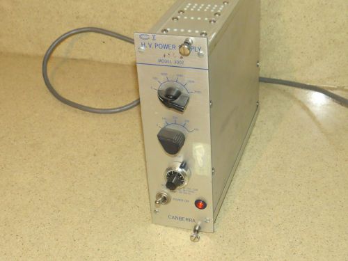
^^ CANBERRA INDUSTRIES CI HV POWER SUPPLY MODEL# 3002
People who viewed this item also vieved
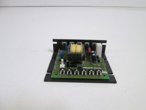
MINARIK SPEED CONTROL MM23001B *NEW OUT OF BOX*
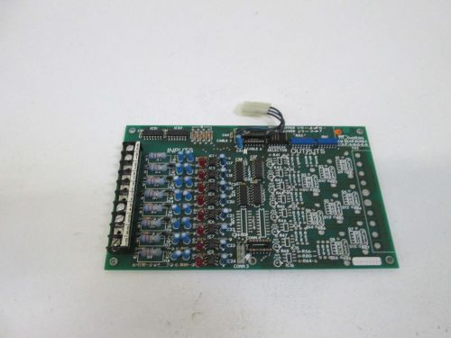
DIVELBISS CONTROL CARD ICM-IO-22 *USED*
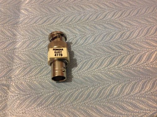
Pomona 4119 50 Ohm BNC Feed-Thru Termination
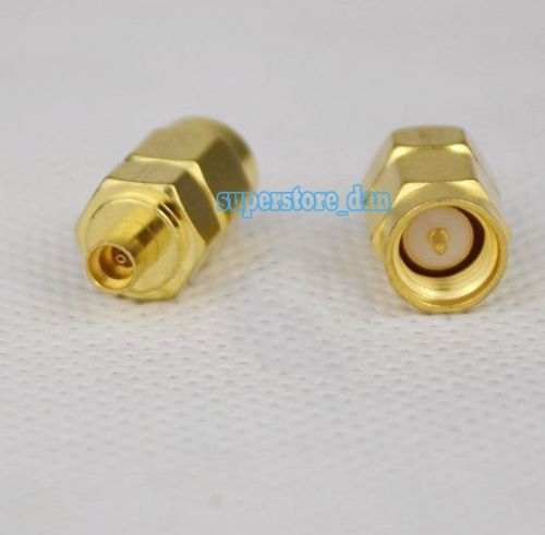
SMA male plug to MMCX female jack RF coaxial adapter connector
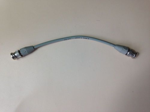
HP / Agilent 10502A BNC Male to BNC Male Cable 8.5"
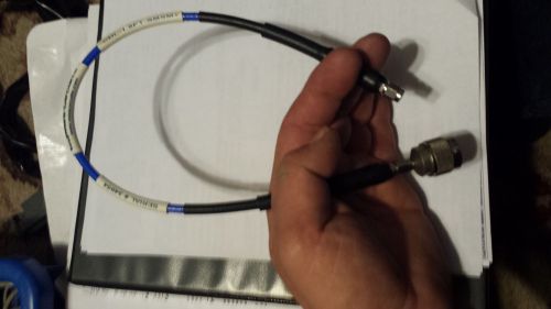
Mini-Circuits CBL-1.5FT-SMSM+ Used Working Condition
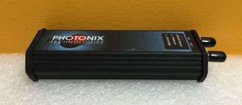
Photonix Technologies PX-C-102 LANlite 850/1300nm ST Port, Dual LED Light Source
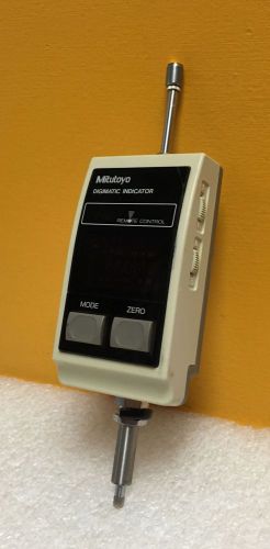
Mitutoyo IDF-1030E 1.2"/30mm Range, 0.001"/0.01mm Accuracy, Digimatic Indicator
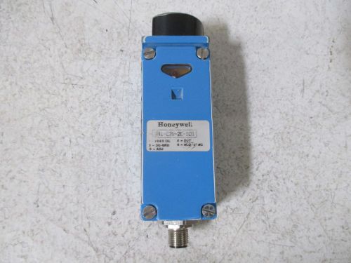
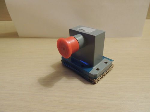
HONEYWELL 941-C2V-2E-1C0 DISTANCE SENSOR *USED*
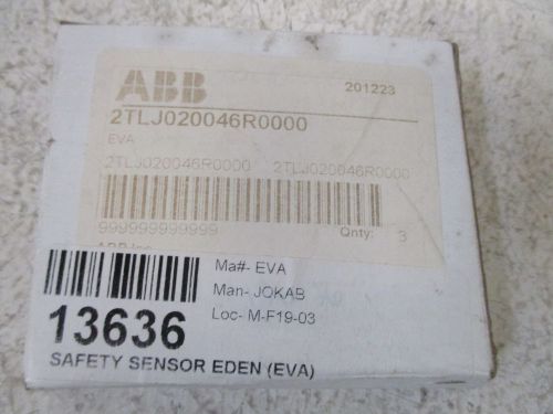
LOT OF 3 ABB 2TLJ020046R0000 SAFETY SENSOR EDEN (EVA) *NEW IN A BOX*
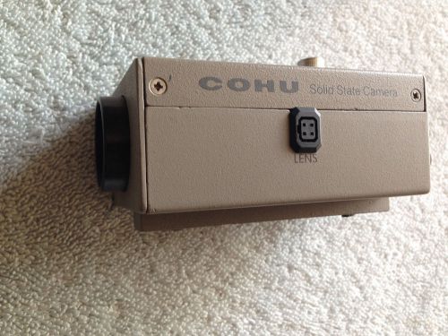
Cohu Solid State Camera Model 2122-2000/0000
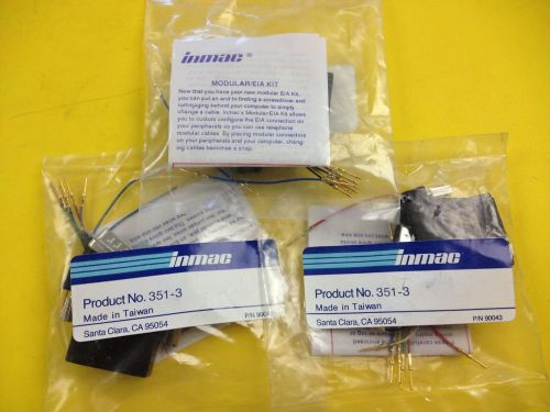
(3) Inmac 90043 PROD NO 351-3 MODULAR EIA KIT NOS IN BAG EIA CONNECTION
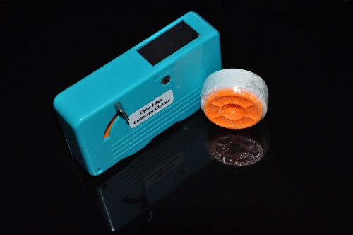
Optic Fiber Connector Cleaner / Cleaning Cassettes Clean per reel over 500 times
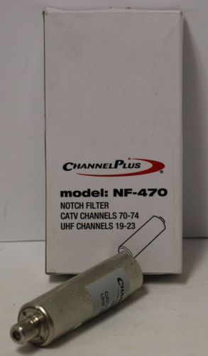
ChannelPlus Notch Filter NF-470 Used
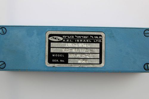
AEL Elisra Band-Pass Filter 135-185MHz MW-1120-37
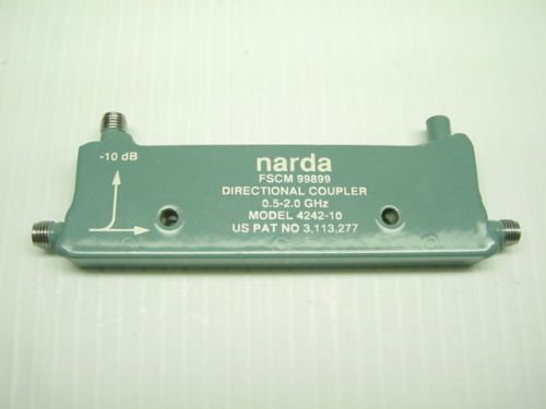
Narda 4242-10 Directional Coupler, 0.5 to 2.0 GHz, 10 dB, SMA(f)
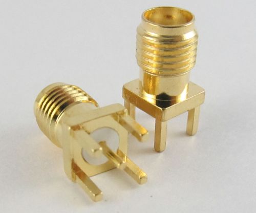
5 pcs SMA RF Female Jack Board Mount Coaxial Connector SS

JFW INDUSTRIES 8 Way Power Divider/Combiner 50PD-456
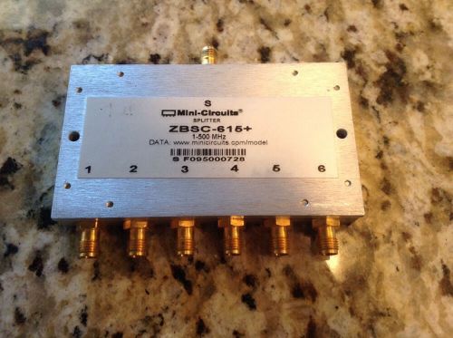
Mini Circuits 15542 ZBSC-615 Power Splitter
2 Motorola WR-137 J-band 5.85-8.20 GHz motorized waveguide automatic switches
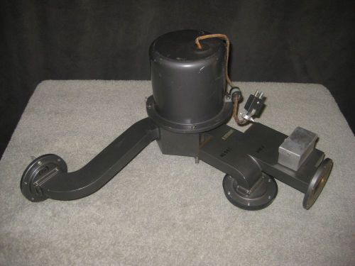
Andrew Waveguide to Coax Transition C137FNDG
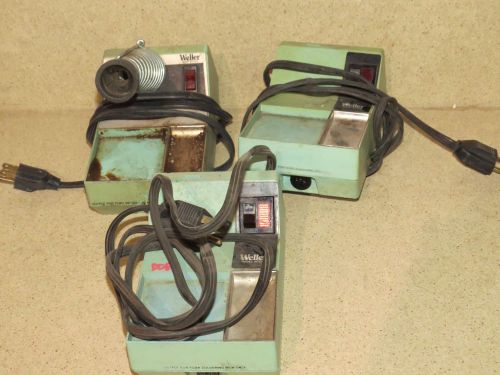
WELLER POWER SUPPLY PART NO TC202 POWER UNIT - LOT OF 3 (WLEE)
By clicking "Accept All Cookies", you agree to the storing of cookies on your device to enhance site navigation, analyze site usage, and assist in our marketing efforts.
Accept All Cookies