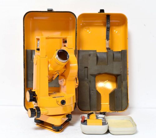
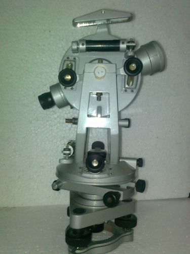
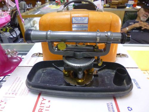
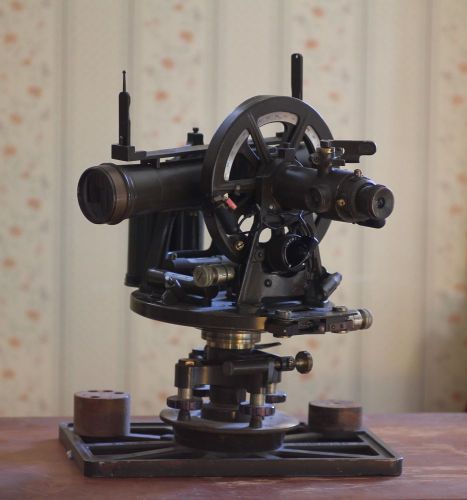
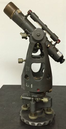
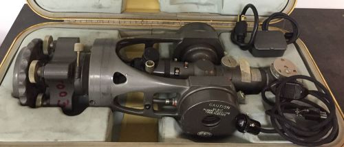
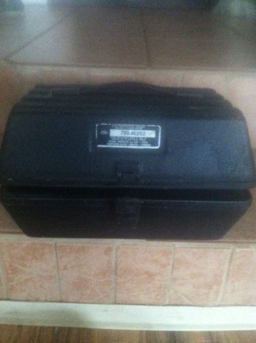
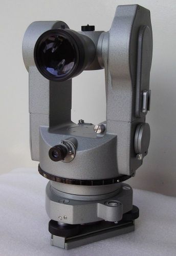
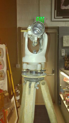
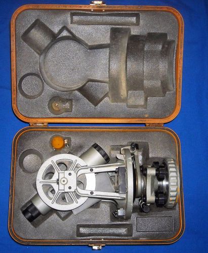
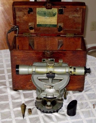
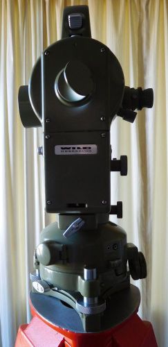
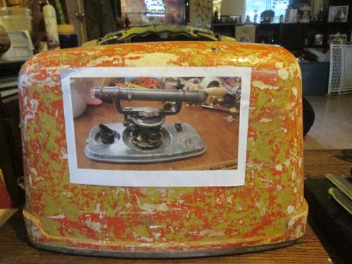
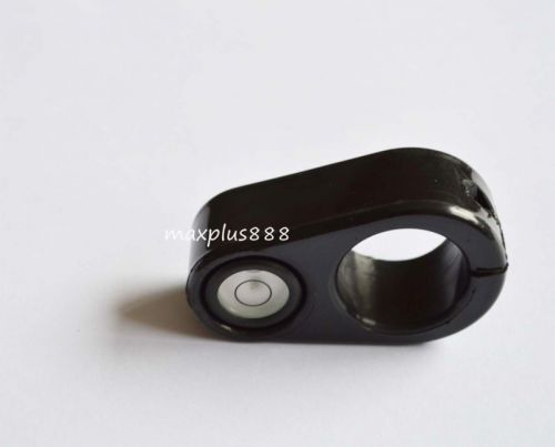
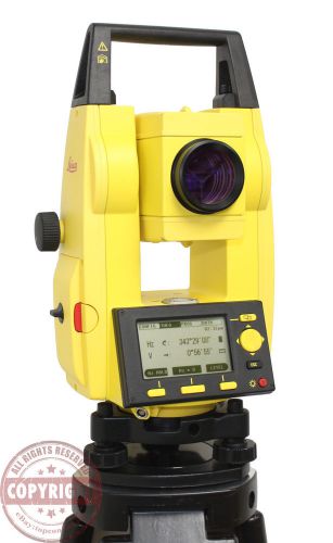
Please see other tools and items which we offer for sale in our store Description: Carl Zeiss Jena Theodolite Model 020B. Made in Germany (GDR) 80" years The theodolite is in very good working condition. Tested. Optic is good. With original Case S.Number - 305155 All work good. ___________________________________________________________________________________________________ DESCRIPTION AND INSTRUCTION FOR THEODOLITE ZEISS THEO 020B _________________________________________________________________________________________________ 1. Technical characteristics Average error of measurement --izmereno two positions of the telescope 1 mgrad (3 ") By three measurement on straight and reverse 0,3 mgrad (1 ") -Zoom 30 times -View Angle 1,3 ° -Looking A distance of 1 km 23 m -Minimal Referred to 1,5 m away -maximal Sight distance when using the rack with inch graduations: --Rules evaluation with precision 0.5 mm 120 m --Rules evaluation with precision 0.5 cm 500 m -Permanent Multiplier 100 Angular error of the cylindrical vial displacement of the bubble of 2mm 30 " -Interval Of graduation grad 1 The value of the division in the reporting scale 10 mgrad Mass of the appliance with a metal box 9 kg 2.Spheres application Rock theodolite THEO 020B is a versatile device suitable for all engineering measurements of angles in two directions, allowing an average error 3 "(1 mgrad) in a single measurement in a direction two positions of the telescope. 3. Description of controls (Figures 1 and 2) 3. Description of controls (Figures 1 and 2) 1. CE orientation of a target mark 2. Handle 3. The bolt handle 4. collimator for rough visual 5. Adjusting gon for Buson (compass with angle measuring device) 6. Protective cap-adjusting screws streak scale 7. eyepiece of the microscope for reporting on the rocks 8. eyepiece of the telescope with dioptriy setting 9. Focus ring (coarse and fine) of the sharpness of the target plate 10. collimator for rough visual setting in at the zenith 11. retainer screw horizontal scale 12. Handle for fixing the horizontal scale 13. Hole adjustment screw lifting screw 14. stopper for fixing the unit on a tripod 15. fixing screws table 16. Lighting mirror 17. bolt handle 18. Lens Telescope 19. Adjustable handle to illuminate the streak scale telescope 20. eyepiece optical projector alignment 21. Screws for leveling 22. Spring plate tripod 23. The main plate of the tripod 24. Allen screws for adjusting the opening of the tripod 25. Screw for fixing on tripod 26. Hook for hanging plumb line 27. Allen screws for securing the legs of the tripod 28. A package tripod 29. micrometer screw targeting height 30. micrometer screw traverse 31. The release lever rotation 32. Handle for inclusion on the testimony of the vertical scale 33. The release lever vertical movement 34. Marking the center bearing telescope 35. Cover the screw to adjust the power to tighten vertical shifting. 4. Operation 4.1. Establishment The device is attached to the tripod with the screw (25) .Before work unit to warm. 4.2. Centering 4.2.1. Centering built optical projector - Tripod settled over the ground point. - The appliance is leveled in the circular level by screws (21). - Optical projector focuses on the eyepiece grid by rotating the eyepiece (20) and on the ground point by turning the eyepiece tube. - Adjust the network ground point as: - The appliance is leveled fine. - The unit is moved in the tray (28) Tripod: 1. in the direction of the two lifting screws 2. in the direction of the third lift screw - In need again leveled. - Check the accuracy of centering in rotation of 180 °. 4.2.2. Centering using a plumb - Repeat the establishment of t. 4.2.1. - It is roughly centered by the tripod legs. - Fine centering is done by moving the tray 28 Centering over the ground point does not depend on leveling the unit. 4.3. Leveling the appliance - Adjust the roughly circular level by screws (21). - Cylindrical vial is placed along the two screws and lifting Turn them by leveling. - The upper part of the device is rotated 90 ° and the level is adjusted to the third screw (bubble moves in the direction of movement of the pointer on the right hand). 4.4. Lighting By rotating and tilting the illuminating mirror (16) is looking for optimal lighting of the rocks. 4.5. Adjusting the contrast of strokes - Direct a telescope at the sky or illuminated white sheet placed angled front of the lens. - Rotates the eyepiece (8) of the telescope until the contrast of strokes. - Remembers settings including to assist in re-work. - Focuses observed object through the ring (9) and the subject must .Shrihite be equally sharp and no parallax. - By turning the eyepiece of the microscope (7) adjusts the contrast of the rocks. 4.6. Endorse - Exempt clamping levers horizontal and vertical movement (31.33). - By collimator (4) is directed roughly telescope. - Fixed to the clamping levers (31,33) They can move separately, but more preferably are together. - It refers to the object by means of micrometer screws horizontal and vertical guidance (29,30). (The last turn of the screw Horizontal movement going clockwise, and screw height c opposite direction). 4.7. Readings on the horizontal and vertical scale In the lower part of the visual field into account the horizontal scale (Hz), and in upper-scale on the vertical (V). Objectives angular units (cities) are reported in this division of the scale, which is located within the fine reporting scale. Hundredth part of the city are reported at fine scale serves as a pointer touches of rough rock. Fractions of the division in the fine scale is estimated to eye. Example reader (Figure 3): V=291,860 gon Hz=372,080 gon Figure.3 To avoid confusion the vertical and horizontal scale are different in color. When measuring only the horizontal edges the vertical scale can be turned off by the handle (32). Errors of parallax, eccentricity of rocks and others. removed by measuring at two positions of the telescope. (After the displacement of several divisions and re-targeting). 4.8. Setting the horizontal scale By pressing the lever (12) creates a connection to the horizontal scale with the upper unit .Then when rotating the top spin and scale and the reading remains constant. By gently pressing the locking lever (11) in the direction of the vertical axis that connection razedinyava.Kogato this option is not used, the compound must be disconnected. Gently press and release the lever and do not apply lateral force! 4.8.1.1. Establish Baseline - Pressed a lever (11) rotates the upper part of the device until a required reading on the scale. - Tighten the lever (31) to rotate. - With a handle (30) finely adjusts the requested indication. - Tighten the lever (12). - Release the lever (31) and refers to the target. - Release the lever again the anchor (12). - Check the sighting and readings on the scale. Fixing in the desired values of indication chosen direction (eg. after orientation compass) eases the work and reduces errors 4.8.1.2. Re-measurement of angles In the re-measurement of angles achieves higher accuracy. - In what is position of the scale refers to the left target point and makes accurate reporting on the scale (and reading). The angle is: A1 = a1- a0 - Tighten the lever (12). - Again referring to the left point (in this indication remains a1). - Push the latch lever (11) and refers to the right point (reading a2ne account). - Repeat the operation for values a3, a4 .... an After an displacements in one direction makes accurate reporting on the scale after targeting the right point. - Calculate the mean: An= . - Release the lever (12) and the telescope is transferred through the zenith. - Targeting the right point. - Reported at the horizontal scale. - The reading differs from the previous example of 180 °, or 200grad. - Determine Al and calculate the average: А= A 1 - the actual angle A r - angle obtained after repeated measurements right Al - angle obtained after repeated measurements left A - angle value after indirect measurement To reach the average accuracy of the device 1 "(0,3 mgrad) e enough triplicate in one direction. 4.9. Measuring distances by rangefinder scale The eyepiece scale urada inflicted rangefinder strokes (Figure 4) to measure distances using vertical or horizontal rack. - Record the section of the strip l between longitudinal touches. - The horizontal distance from the point in which stands the unit to the rack is: S = 100.l.sin v. - For horizontal rack of the formula is: S = 100.l.sin v, where v is the zenith angle of reporting on the vertical scale. What a super addition to any collection ~ just waiting to be displayed or used. Good Luck & Happy Treasure Hunting! See photos for actual condition and contact with me for everything you want to know about this item ------------------------------------------------- See carefully photos. You will received what you see on photos. We will answer all your questions. Visit our store . combine shipping - we ship worldwide Thank you ______________________________________________________________________ Only PayPal is Accepted / Available funds. Payment is required 1-2 days after purchase. Item will be shipped immediately on the same or next business day of receiving clear and payment. We Ship With Registered Mail (Tracking Number) Paypal Confirmed Addresses Only Tracking Number Will Be Provided To The 24-48 Hours We make sure your package is safely packed! About us: We offered you vintage Germany and Russian items, tools and so on. Photography and Surveying equipment ! All of our products are Authentic. We will describe our products as much as we can. ECONOMY DELIVERY FOR USA and other International ESTIMATED WITHIN 8-25 BUSINESS DAYS, SOMETIMES 28-41 DAYS OR MORE - VARY TIME [ International buyers are responsible for any taxes or duty fees their specific country will levy on the package ]
By clicking "Accept All Cookies", you agree to the storing of cookies on your device to enhance site navigation, analyze site usage, and assist in our marketing efforts.