US $1000
Directions
Similar products from Satellite and Radar Testing Equipment
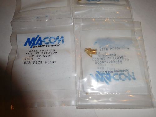
Qty 8 MACOM 2002-5015-00 SMA F TO 0.141
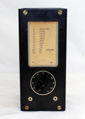
Vintage Steampunk Capacitor Substitution Box
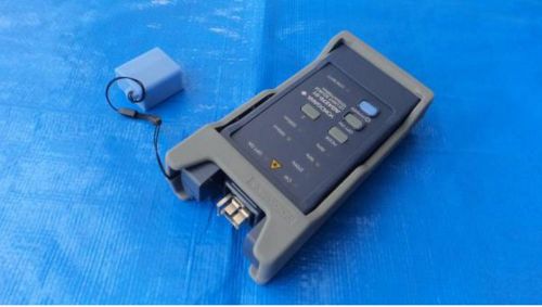
Yokogawa AQ4270-01 LD Light Source 1310nm/1550nm
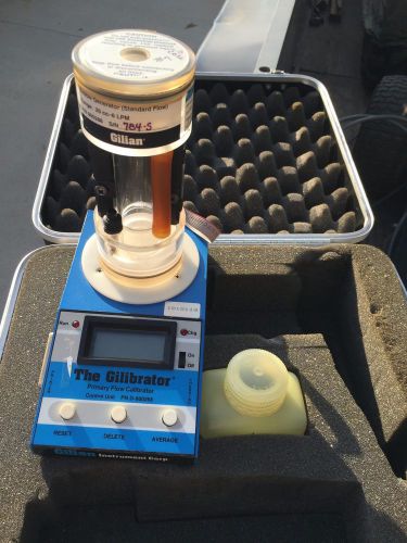
Gilian Gilibrator with 20CC-6LPM and case
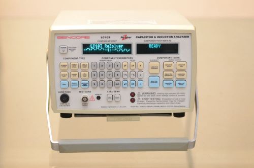
Sencore LC103 Capacitor Inductor Analyzer
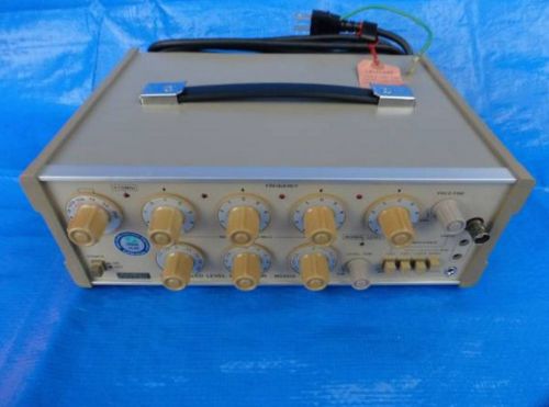
Anritsu SYNTHESIZED LEVEL GENERATOR MG442A
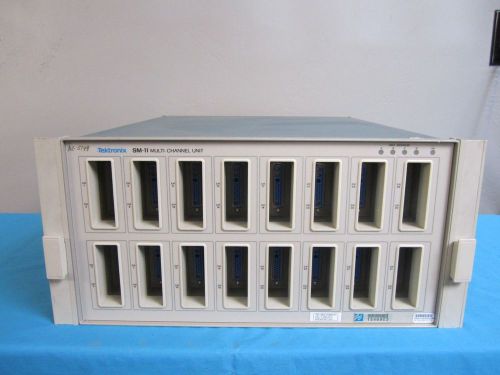
Tektroinx SM-11 Mutli-Channel Unit
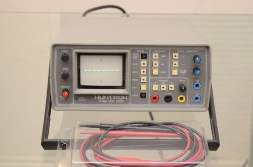
Huntron Tracker 2000 Electronic Component Tester Circuit Analyzer
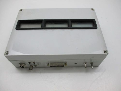
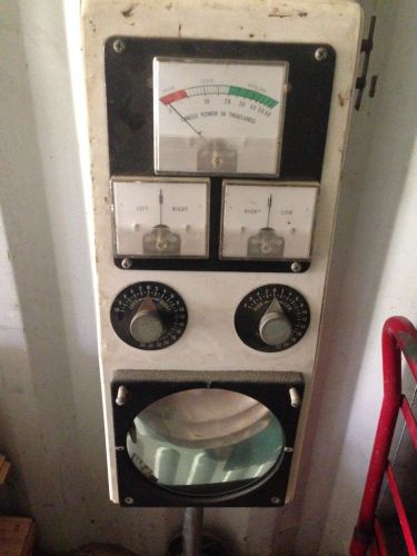
Hydrographic Survey Products Universal Helmsman Display Model 14C
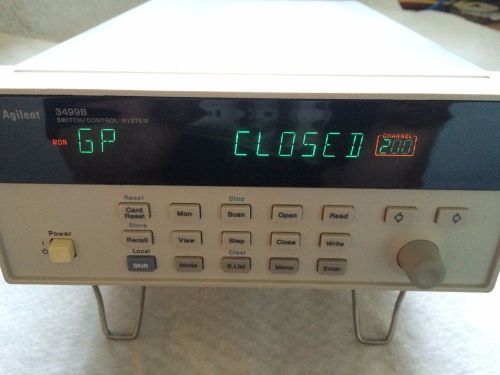
Agilent Control Switch Mainframe 3499B and DC-18GHz Microwave Switch 44476A
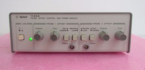
HP / Agilent / Keysight 1143A Probe Offset Control & Power Supply Module USED-I
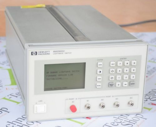
HP/Agilent 86060C Lightwave Switch Opt 001 012 050 109 204 UK6
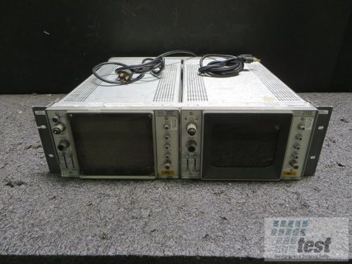
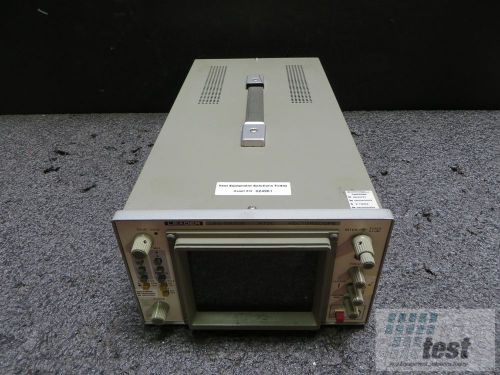
Tektronix 1420 / 1421 Vectorscope A/N 25001 SE
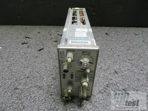
Tektronix 7A26 Dual Trace Amplifier A/N 24944 SE
Leader LVS-5850B NTSC Vectorscope A/N 24961 SE
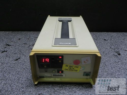
Fluke 2300A Scanner A/N 24972 SE
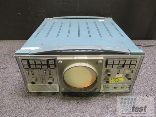
Tektronix 520 NTSC Vectorscope A/N 24957 SE
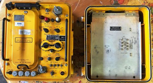
RARE TIC Tel Instrument Transponder Test Set TS-1809 AN/APM-123 (V) with Case

Dynamic Structures DSM VF-500 Hi-Power Linear Piezoelectric Amplifier Piezo Amp!
People who viewed this item also vieved
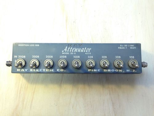
KAY Attenuator Model 30-0 432 D
Sencore SG80 am fm stereo analyzer
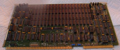
intel 012B/056B Rev P BJ PWA 112642-026 Board
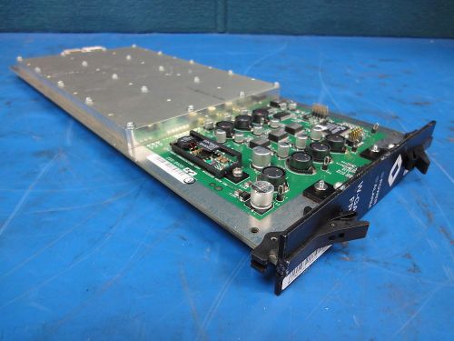
METAWAVE 250-04535-03 WIDEBAND GAIN FRU
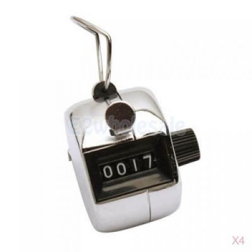
4x Handy Sport Match Tally Counter NO. Clicker 4Digits Count Range 0000 to 9999
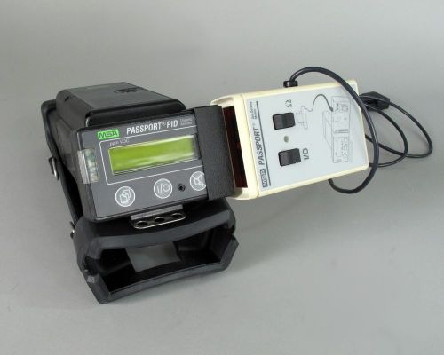
MSA Passport PID 2 II Organic Vapor Monitor w/ Organic Docking Module
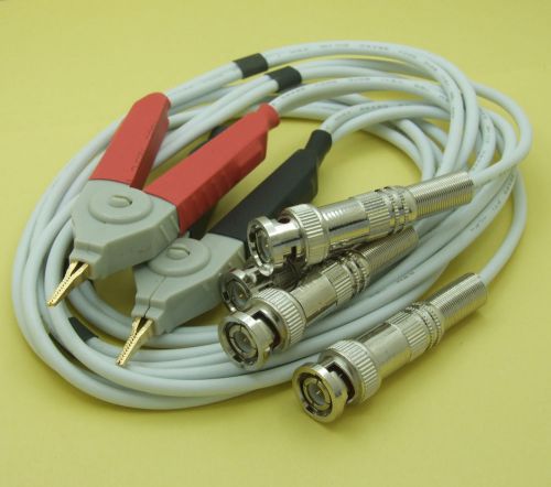
1 Set Kelvin Clip Wires for 4 BNC TO Alligator clip LCR Meter with 4 BNC Test
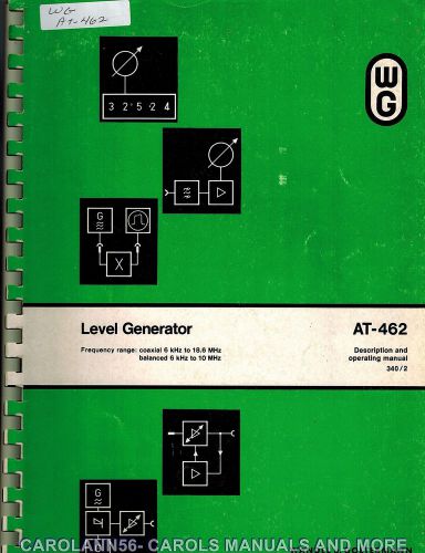
WG Manual AT-462 Level Generator
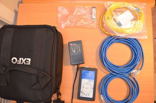
EXFO EST1000L Fiber Testing Kit
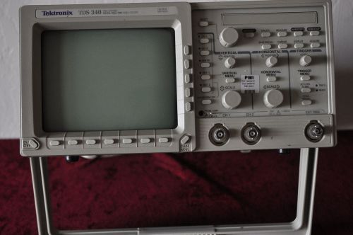
Tektronix TDS 340 100MHz 2Channels Digital Real Time Oscilloscope
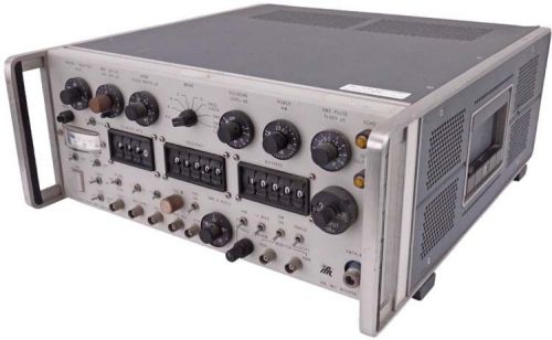
IFR ATC-1200Y3 XPDR/DME Simulator Transponder Bench Test Set Analyzer
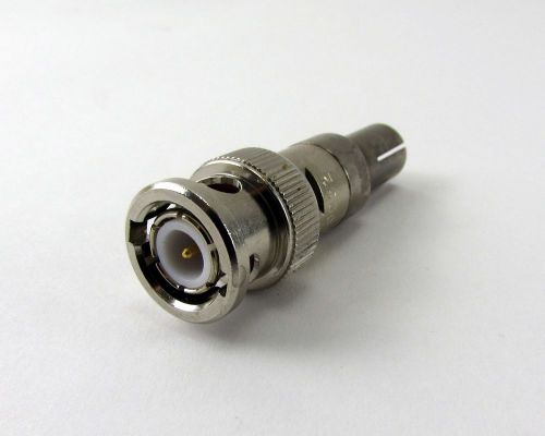
HP / Agilent 10218A BNC to Probe Tip Adapter 1250-0052 for 10020A, 10821A *NEW*
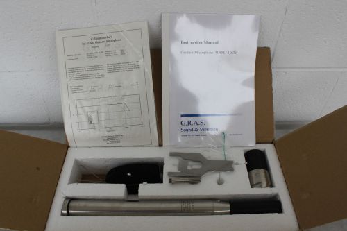
GRAS Type 41AM Sound & Vibration Microphone #5 Made In Denmark
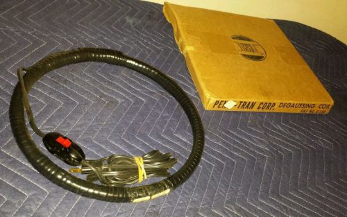
PENN_TRAN CORP. Degaussing Coil C-100 Eliminates Magnetic fields in CRT Screen
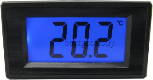
-50-150°C Digital Blue backlight LCD Thermometer temperature temp dislpaly
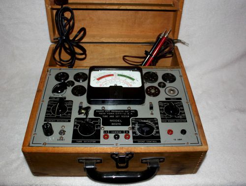
Vintage Radio City tube tester w/ original cord, test leads, Manual, schematic
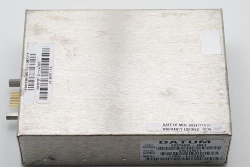
The Datum LPRO-101 10MHZ Frequency Standard Rubidum Oscillator
By clicking "Accept All Cookies", you agree to the storing of cookies on your device to enhance site navigation, analyze site usage, and assist in our marketing efforts.
Accept All Cookies