US $250
Directions
Similar products from Maintenance & Supporting Tools for Electronic Components
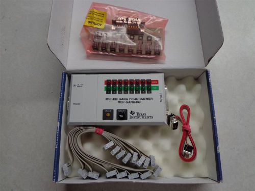
Texas Instruments MSP430 Gang Programmer MSP-GANG430
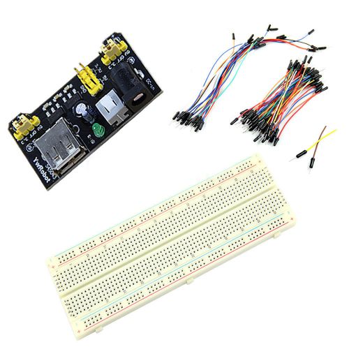
MB102 Power Supply Module 3.3V 5V+Breadboard Board 830 Point+65PCS Jumper cable
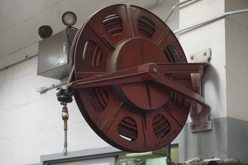
Vintage Appleton AIREEL Hose Reel 30" Wheel Spring-Loaded $290 Or Best Offer
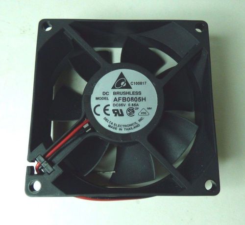
Delta Electronics DC Brushless Fan AFB0805H DC05V 0.65A
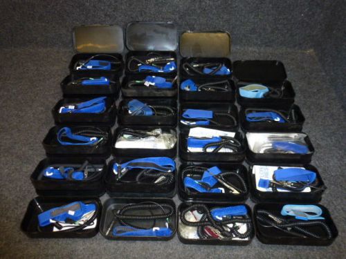
LOT of (23) ANTI-STATIC WRIST STRAP ASSEMBLIES / PATLON INDUSTRIES, PA 0360-10C
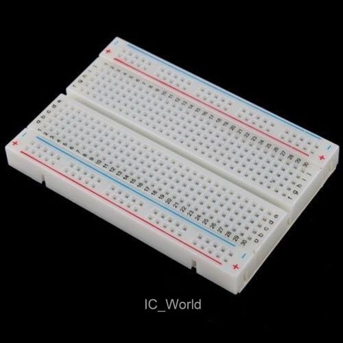
Mini Solderless Breadboard 400 Contact Tie-Points Electronic Test Deck Prototype
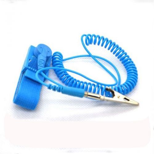
Brand Anti Static ESD Wrist Strap Discharge Band Grounding Prevent Static Fine
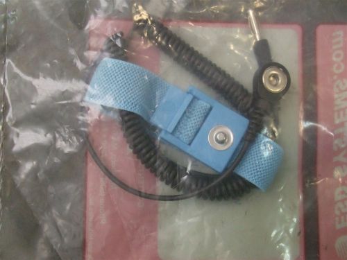
Quantity 1 pc - ESD Antistatic Personal Grounding Wristband Strap
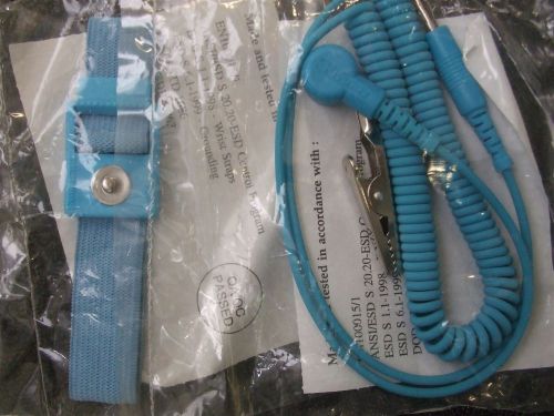
Quantity 1 pc - Antistatic Personal Grounding Wristband Strap
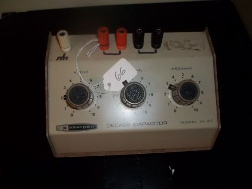
USED HEATHKIT DECADE CAPACITOR MODEL IN-27
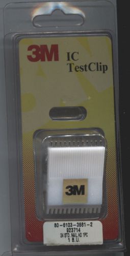
New, 3M IC Test Clip, 24 Pin DIP, Nail Head Test Points
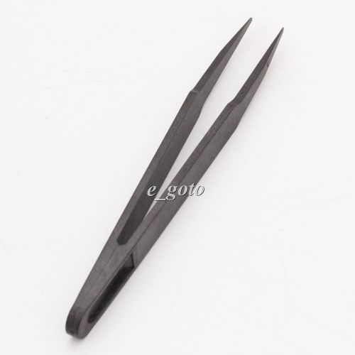
Black Anti static Plastic tweezers 93003 Tweezers ESD Conductive Plastic Tweezer
Hakko CHP 00-SA Fine-Tip Tweezers, Straight, Flat Tips, Non-Magnetic Stainless
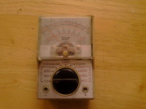
Eico 1A1 Mini Mutimeter "AS IS"
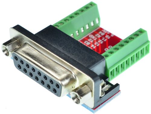
DB15 Female Breakout Board, adapter, D-Sub 15pin, (Female) eLabGuy D15-F-BO-V2A
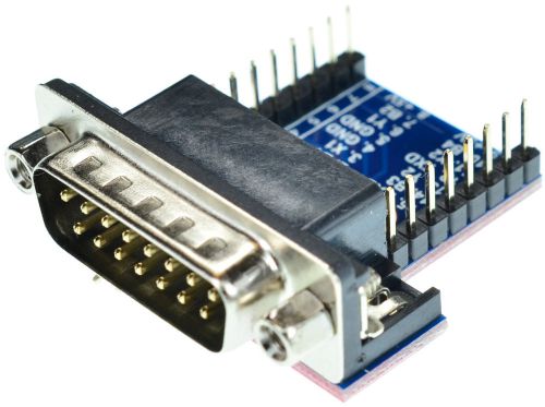
DB15 Male Breakout Board, adapter, D-Sub 15pin, (Male) eLabGuy D15-M-BO-V2A
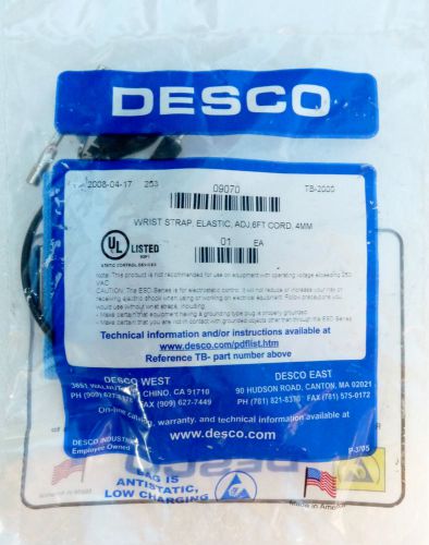
NEW DESCO 09070 WRIST STRAP ADJUSTABLE ELASTIC GROUND GROUNDING 6' CORD 4MM
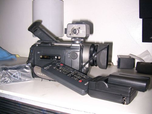
Sony Digital Camcorder Model DSR-PD100A DVCAM
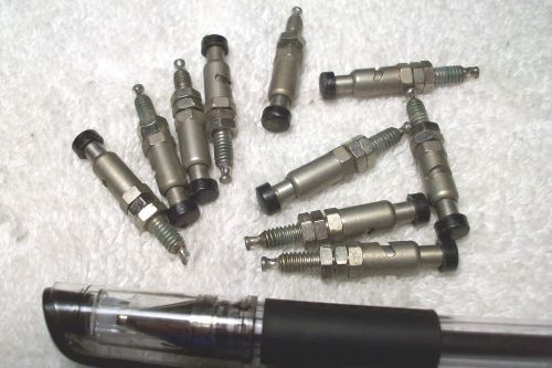
Spring loaded binding post Panel mount Test Hook Terminal Connector Qty 10
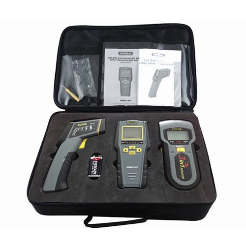
General KT100 Restoration Kit (MSV100, IRTC50 and MMD7NP)
People who viewed this item also vieved
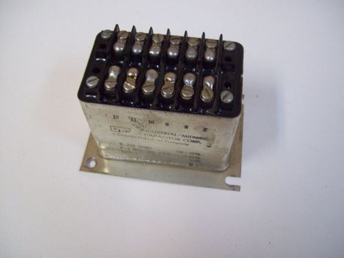
INDUSTRIAL MIDWEC 709913 CAPACITOR - FREE SHIPPING!!!
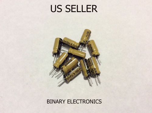
20pcs Nichicon 4.7uF 50v Low Leakage Radial Electrolytic Capacitor USA SELLER
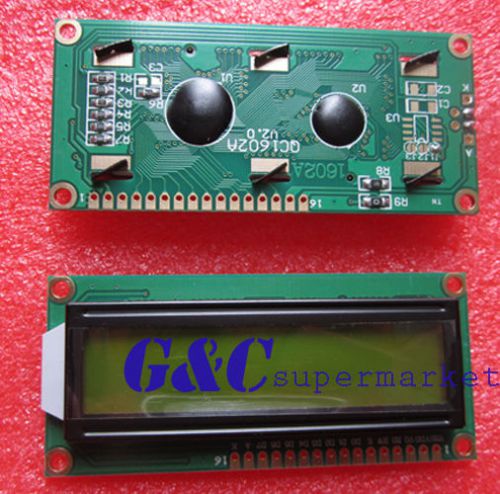
2PCS 1602 16x2 HD44780 Character LCD Display Module LCM Yellow backlight
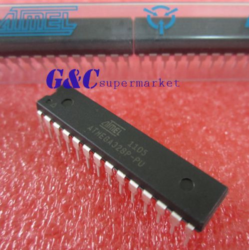
5PCS ATMEGA328P-PU DIP-20 Microcontroller NEW DATE CODE:12+
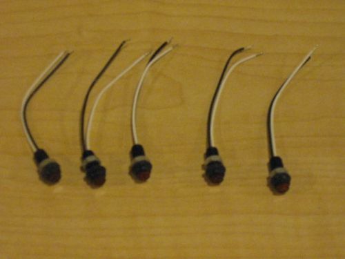
LEDs for Electronics Projects - 5 Pieces - Red - With Mounting Nut
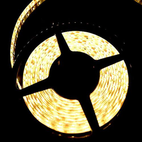
Wholesales 10PCS 5M 3528 300 LED SMD Warm White LED Strip Light IP65 Waterproof
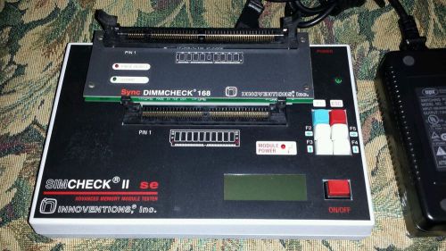
SIMCHECK II SE Advanced Memory module Tester
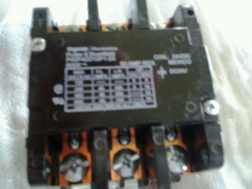
Tyco potter & brumfield p40p42d12p1-24 3 poles 600v 50 amp res. Coil: 24vdc
1xE88CC Telefunken made in Germany Amplitrex AT1000 Tested #1108001
1pair ECC83 Brimar made in U.K. Amplitrex AT1000 Tested #1100001&1103001
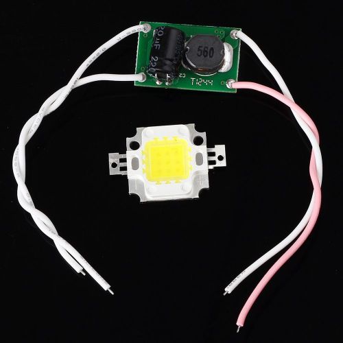
High Power 10W 9-12V DC White LED Light Bulb 900-1000LM + DC12V-24V Driver
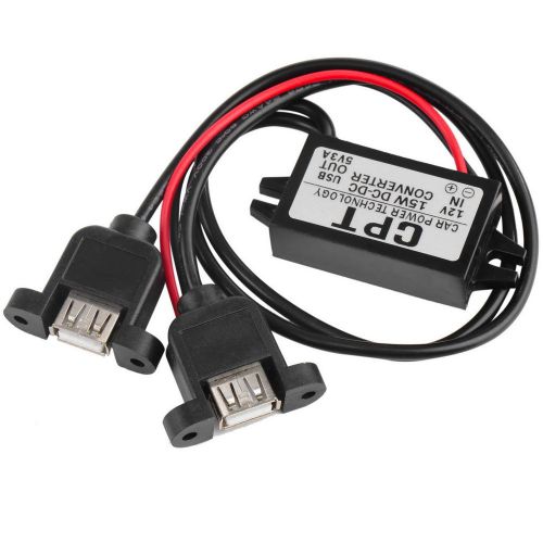
DC DC Converter Module 12V To 5V 3A 15W Duble USB Output Power Adapter EC
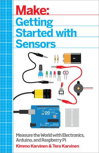
Make: Getting Started with Sensors PDF

By clicking "Accept All Cookies", you agree to the storing of cookies on your device to enhance site navigation, analyze site usage, and assist in our marketing efforts.
Accept All Cookies