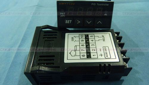
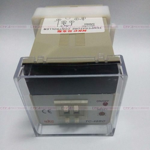
PID TEMPERATURE CONTROLLER INSTRUCTION MANUAL It's compatible with : Gongzheng Thunder-jet Litu Sky-color Xuli etc DX5 DX7 Solvent and UV Inkjet Printers . Caution This troller is intended to control equipment under normal operating conditions. If failure or malfunction of it could lead to an abnormal operating condition that could cause personal injury or damage to the equipment or other property, other devices (limit or safety controls) or systems (alarm or supervisory) intended to warn of or protect against failure or malfunction of the controller must be incorporated into and maintained as part of the control system. The front panel (Display and Key buttons) are dust and splash proof. Additional protection IP rating and performance This controller carries a 1 year warranty against manufacturer defacts repair and replacement of parts (except wear and tare items) at our factory is free Of Change during the warranty period. 1. Specification Input type Thermocouple (TC): K, E, S, R, J, T, B, WRe3/25 RTD (Resistance temperature detector): Pt100, Cu50 Input range See table 2 Display Bright LED, red, four digits, degree F or degree C measuring unit Display resolution 1degree C, 1degree F, or 0.1degree C, 0.1degree F with Pt100 Accuracy ±0.2% or ±1 unit Control mode PID, with Over or Under temperature alarm output Output mode 8VDC,30mA(short circuit),for driving SSR module Relay contacts Max,250Vac,3A resistive load,<10000switch cycles Operating ambient 0-50 degree C ,<RH85% Power supply 85~260VAC/50~60Hz or 85-260VDC Power<2 Watts Dimension 24x48x75mm (1/32 DIN), (mounting cutout 45x22 mm) 2. Front Panel and Operation Thermocouple sensor (left) and RTD sensor (right) 3.1 Installation 3.1.1 Thermocouple The thermocouple should be connected to terminals 6 and 7. Make sure that the polarity is correct. There are two commonly used color codes for the K type thermocouple: US color code uses yellow (positive) and red (negative). Imported DIN color code uses red (positive) and green/blue (negative). 3.1.2 RTD sensor For a three-wire RTD with standard DIN color code, the two red wires should be connected to the terminals 6 and 7. The white wire should be connected to terminal 8. For a two-wire RTD, the wires should be connected to terminals 7 and 8. Jump a wire between terminals 6 and 7. Set controller input type, <Inty>, to P100 (1 degree resolution) or P10.0 (0.1 degree resolution). 3.2 Power to the controller The power cables should be connected to terminals 1 and 2. It can be powered by 85 - 260V AC or DC power source (50/60Hz). The casing is plastic and therefore no Ground terminal is needed. 3.3 Output connection Two outputs are offered: (1) The SSR control (9 & 10) has an 8V DC voltage for driving SSR module, 30mA output current at short circuit. Connect terminal 9 to the negative input and terminal 10 to the positive input of the SSR, Set the (PW0089) on <outy>, to 2, 3 or 6 if SSR is used. (2) The relay contacts J1 (4 & 5) can be used to turn on a contactor, heater, valve, or external devices, together with an external source (voltages) 4. Parameter Setting For safety reasons, the controller parameters are divided into three groups with different pass codes. You should only give the code to those who have the responsibility and knowledge of how to properly change it. Code 0089 contains the parameters for system configuration that may need to change during the initial set up. Code 0036 contains the parameters for tuning performance. Code 0001 is for controlling temperature and alarm settings. 4.1 System Configuration Parameters The system configuration parameter s is listed in table 1. To change the parameters, press "set", enter code "0089" press "set" again. Then, follow the flow chart (1) Press "set" to enter setting mode; (2) Press ">","up" and "down" to enter parameters; (3) Press "set" to confirm; (4) Press "up" or "down" to select the new parameter. 4.2 PID Parameters The PID parameters are listed in table 3. To change the parameters, press "set", enter code "0036", press "set" again. Table. 1. System configuration parameters Code Description Parameters Initial Note Inty Input Sensor type See table of Description of initial function value K 1 outy Control Output mode 0, 1, 2, 3, 4 2 2 hy Control Hysteresis 0~9999 3 3 Psb Input Shift Adjustment -1000~1000 0 rd Heat cold 0 heat;1 cold 0 CorF Unit select 0 degree C;1 F 1 End The End Note 1. The controller is preset for K type thermocouple input. If any other type of sensor is used, the Inty value needs to be changed to the corresponding symbol as shown in Table 2. Table 2. Temperature sensor code name Input spec. Setting Range(degree C) t T type Thermocouple -200~400 Resistor input 100K r R type Thermocouple -50~1600 J J type Thermocouple -200~1200 W WRE 0~2300 b B type Thermocouple 350~1800 S S type Thermocouple -50~1600 K K type Thermocouple -200~1300 E E type Thermocouple -200~900 Current output 0.2mA Pt100 P100 -199~600 Pt10.0 P100 -199.9~600.0 Cu50 Cu50 -50.0~150.0 Note 2. The value of outy determines the control mode. When it is set to: 0 - Relay J1 as alarm output; SSR output disabled. 1 - Relay J1 as PID controlled relay contact output; SSR output disabled. 2 - Relay J1 as alarm output; SSR PID control output. 3 - Relay J1 as alarm output; SSR On/off control output. 4 - J1 as On/off control relay contactor output. SSR output disabled. 5 - J1 as Limit control output. 6 ? Relay J1 as alarm output; SSR for Limit control output. Table 3. PID and relevant parameters symbol Name Description parameters Initial P P Proportional band 0.1~99.9% 5.0 I I Time of Integral 2~1999(s) 100 D D Time of Derivative 0~399(s) 20 SOUF SOUF Overshoot depressant 0.0~1.0 0.2 OT OT Control period 2~199(s) 2 Flit Flit Input digital filter 0~3 0 End End The End Note 3. Hysteresis Band (also called dead band, or differential), Hy, is used for on/off control and limit control. Its unit is in degrees (degree C or degree F). For on/off control mode, the output will be off when PV>SV and on again when PV <SV-Hy for heating. For cooling, the output will be off when PV<SV and on again when PV>SV+Hy. For limit control mode, the controller can not be reset (to turn on the output) when PV>SV-Hy for heating, and when PV< SV+Hy for cooling. 4.3 Temperature setting and Alarm setting The temperature and alarm parameters are listed in table 4. To change the parameters, press "set", enter code "0001", press "set" again. Figure 5 is the parameter flow chart. Note 4. The autotune offset will shift the SV value down by the Atdu value during the auto tune process. That will prevent the system from damage due to overheating during the autotune. The values of the P, I, and D parameters are critical for good response time, accuracy and stability of the system. Using the Auto-Tune function to automatically determine these parameters is recommended for the first time user. If the auto tuning result is not satisfactory, you can manually fine-tune the PID constants for improved performance. Note 5. Proportional Constant (P): P is also called the proportional band. Its unit is the percentage of the temperature range. E.g. for a K type thermocouple, the control range is 1500 degree C. P=5 means the proportional band is 75 degree C (1500x5%). Assuming the set temperature (SV) = 200. When integral, I, and derivative, d, actions are removed - the controller output power will change from 100% to 0% when temperature increases from 125 to 200 degree C. The smaller the P value is, the stronger action will be for the same temperature difference between SV and PV. Note 6. Integral time (I): Brings the system up to the set value by adding to the output that is proportional to how far the process value (PV) is from the set value (SV) and how long it has been there. When I decrease, the response speed is faster but the system is less stable. When I increase, the response speed is slower, but the system is more stable. When I=0, the integration is turned off. It becomes to a PD controller that is useful for very slow system. Note 7. Derivative time (d): Responds to the rate of PV change, so that the controller can compensate in advance before |SV-PV| gets too big. A larger number increases its action. Setting d-value too small or too large would decrease system stability, causing oscillation or even non-convergence. Normally, d is set to 1/4 of the I value. Note 8. Damp constant: This constant can help the PID controller further to improve the control quality. It uses artificial intelligence to dampen the temperature overshot. When its value is too low, the system may overshot. When its value is too high, the system will be over damped Note 9. Cycle rate (ot): It is the time period (in seconds) that the controller uses to calculate its output. E. g. If ot=2, and the controller output is set to 10%, the heater will be on 0.2 s e c o n d and off 1.8 second s for every 2 seconds. Smaller ot value results in more precision control. For SSR output, ot is normally set at 2. For relay or contactor output, it should be set longer to prevent contacts from wearing out too soon. It normally set to 20~30 seconds. Note 10. Digital Filter (Filt): Filt=0, filter disabled; Filt=1, weak filtering effect; Filt=3, strongest filtering effect. Stronger filtering increases the stability of the readout display, but causes more delay in the response to change in temperature Table 4. Temperature and alarm parameters Symbol Description Initial Setting Note SV Target temperature (Set Value) 800 11 AH1 Heat-control, Low alarm@ 800 12 AL1 Cooling-control Hi-alarm@ 900 12 End Exit 5. Auto-Tuning The auto-Tuning function (also called self tuning) can automatically optimize the PID parameters for the system. The auto-tuning function will use the on/off mode to heat up the system until it passes the set point. Then let it cool down. It will repeat this about three times. Based on the response time of the system, the built-in artificial intelligence program will calculate and set the PID parameters for the controller. If your system has a very slow response, the auto tuning could take a long time. 5.1 To activate auto-tuning, press and hold> key until the "AT" indicator starts to blink, which indicates auto-tuning is in progress. When "AT" stops blinking, the auto-tuning is finished. Now, newly calculated PID parameters are set and used for the system. Please note that auto-tuning is only for PID control mode (when "outy" is set at 1 or 2). 5.2 To stop the auto-tuning, press and hold "set" key until "AT" indicator stops blinking. Then, the previous PID parameters values are resumed. Note 11. There are two ways to set the target temperature During the normal operation mode press ?up? or ?down? once to switch the display from PV to SV .the display will start to blink, press ?up? or ?down? again to increase or decrease the SV .When finished, wait 8 seconds and the setting will take effect automatically(the display will stop blinking). Follow the flow chart shown; this method is easier for large temperature change. If no key is pressed after confirmation of SV, the controller will return to normal operation mode automatically in 1 minute. Note 12. Relay Contacts setting, When the SSR is used as the control output, Relay Contacts can be used as an alarm output (set<outy>=0,2or,3) It can be set to "Below" or "ABOVE" alarm by AH1 and AL1 (set by PW=0001). If AH1>AL1, J1 contacts CLOSED when read out temperature>AL1, If AH1<AL1, J1 contacts CLOSED when read out temperature<AH1.
By clicking "Accept All Cookies", you agree to the storing of cookies on your device to enhance site navigation, analyze site usage, and assist in our marketing efforts.