


US $456.00
| Condition | Used
:
An item that has been used previously. The item may have some signs of cosmetic wear, but is fully operational and functions as intended. This item may be a floor model or store return that has been used. See the seller’s listing for full details and description of any imperfections.
|
| Seller Notes | “As seen in pictures” |
Directions
Similar products from Optical Power Meters, Fault Locators & Testers
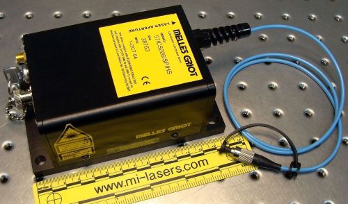
NEW MELLES GRIOT DIODE LAB LASER with FC FIBER OPTIC and MODULATION 782nm, 26mW
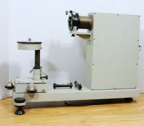
CST/berger AOTOLEVEL CALIBRATOR COLLIMATOR Autolevel TESTING TOOL
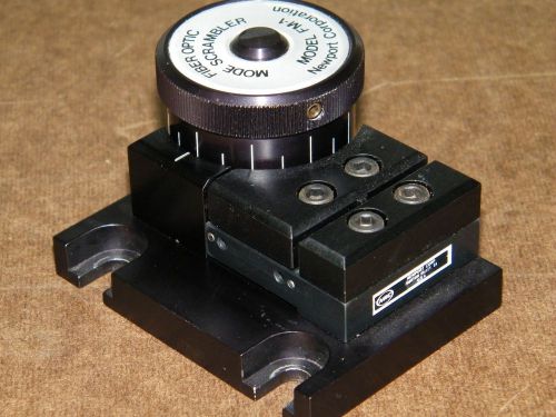
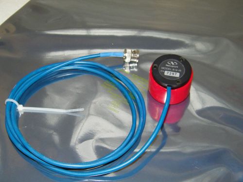
Newport NRC FM-1 Fiber Optic Mode Scrambler
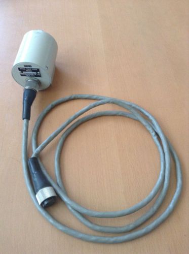
Anritsu Optical Power Sensor MA96A (option 22)
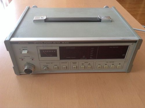
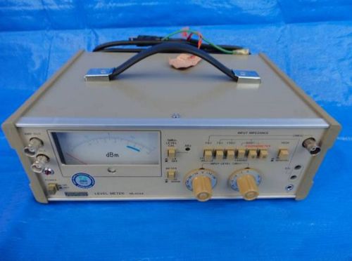
Anritsu Optical Power Meter ML93B
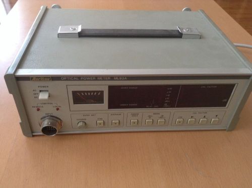
Anritsu Optical Power Meter ML93A
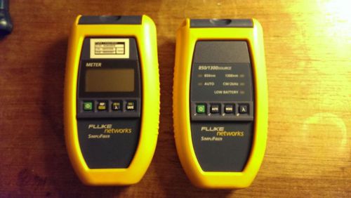
Fluke Networks FTK150 SimpliFiber MM Fiber Optic
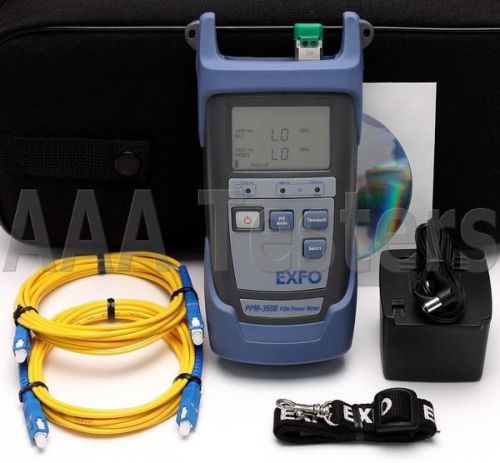
EXFO PPM-350B SM Fiber PON Power Meter FTTx PPM-350 PPM-351B PPM-351B-EA-VZ1
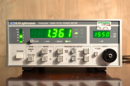
Newport / ILX Lightwave FPM-8200 Fiber Optic Power Meter
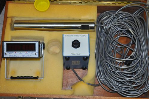
Mark Tech Alignment Telescope System
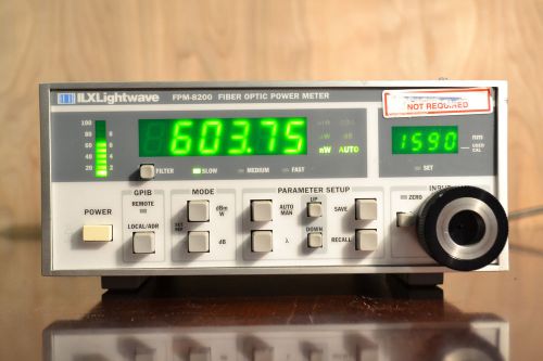
Newport / ILX Lightwave FPM-8200 Fiber Optic Power Meter - Large Fiber Input
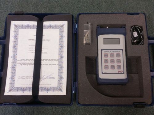
FIS 9101-8513 OV-2 FIBER OPTIC VERIFIER
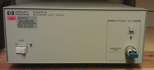
Agilent HP 83437A Broadband light source1550nm opt. 001
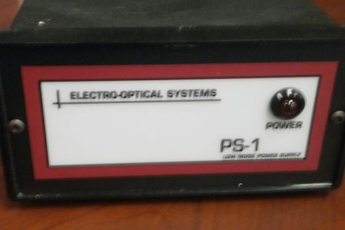
Electro-Optical Systems Inc. PS-1 Low Noise Power Supply
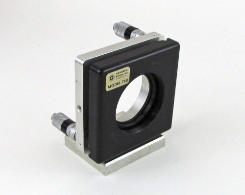
Coherent Model 760 2-Axis Optics Mount / Positioner - Mirrors, Filters, Etc.
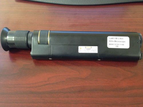
Westover Scientific FM-C400, 400x Fiber Microscope
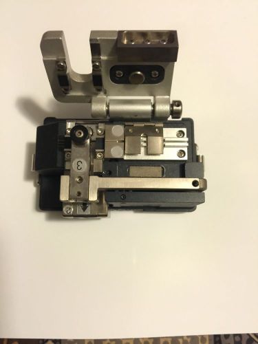
Fujikura CT-04b Precision Cleaver
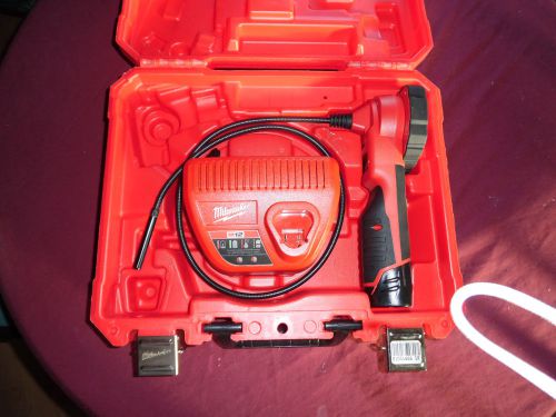
milwaukee m12 spector 2313-20 SERIAL #D5A014024451 12V
People who viewed this item also vieved
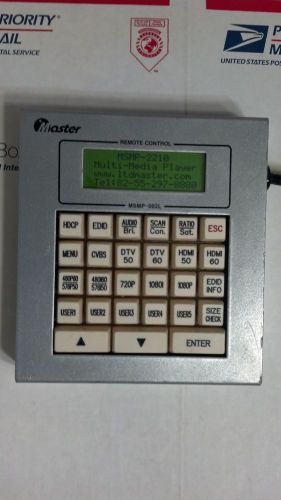
Master MSMP-002L Remote Control Inv#ANG099
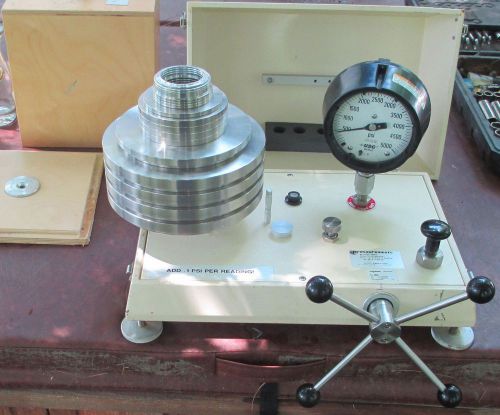
FLUKE Pressurements Dead Weight Tester 5-500 psi Water unit with weights
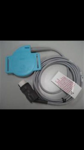
TOCO COROMETRICS FETAL MONITOR TRANSDUCER
Velleman CA083 6P, 240° DIN PLUG - BLACK
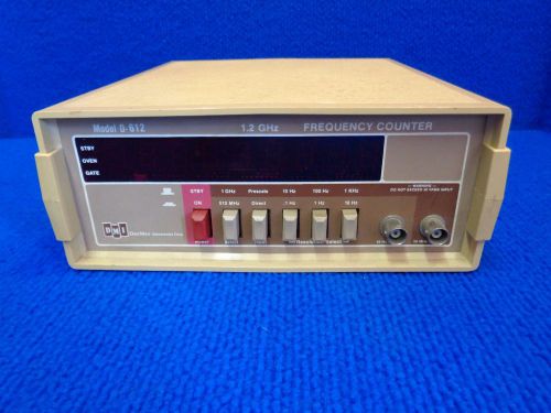
Vintage DMI Frequency Counter 1.2 GHz D-612 "Untested"
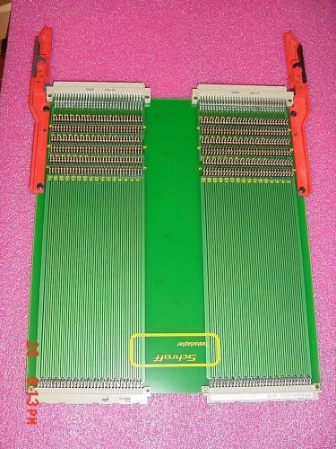
Schroff 20800-188 VME Board ExtenderTestadapter
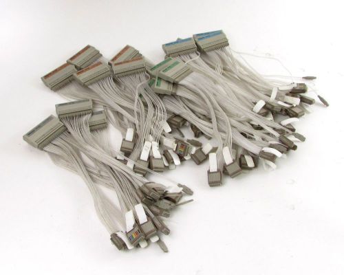
Lot of (17) Tektronix 92A96 Probe Interface Housings w/ (3) 8-Channel Probes Ea.
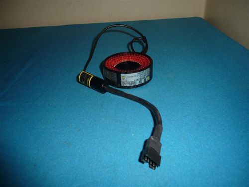
Moritex MDRL-CR31 LED Ring Illuminator
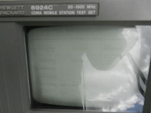
Hewlett Packard Hp 8924c and Hewlett Packard Hp 8924e CDMA MS SERVICE TEST SETS
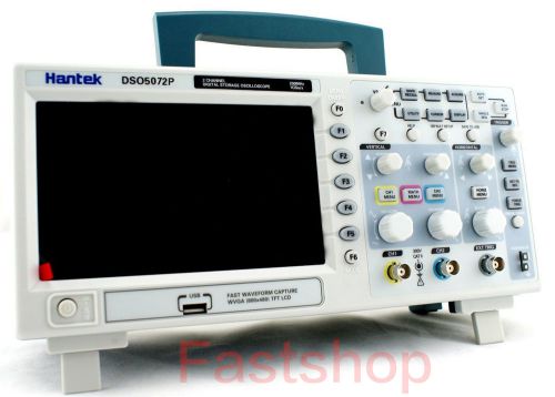
New DSO5202P Hantek Digital Oscilloscope 200MHz 1Ghz 2CH 7" TFT WVGA 800x480
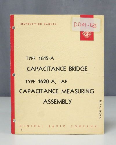
General Radio Type 1615-A & 1620-A, -AP Capacitance Bridge Instruction Manual
Triplet 3413 Tube Tester Vintage Made In USA Tested Working
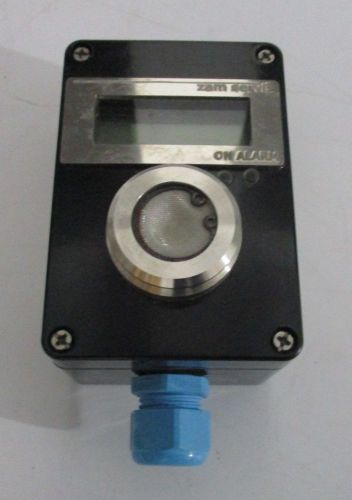
ZAM SERVIS Stationery Detector of combustible & Toxic Gases, Complete Kit
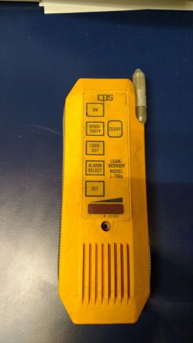
CPS Products, model L-790A, leak seeker
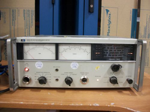
HP 4815A RF Vector Impedance Meter
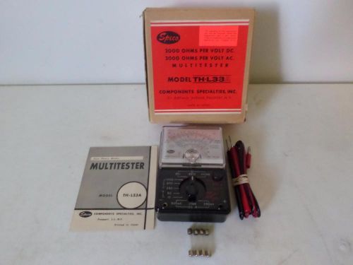
VINTAGE SPECO MODEL TH-L33A METER MULTITESTER 2000 OHMS WORKS GREAT VERY CLEAN!!
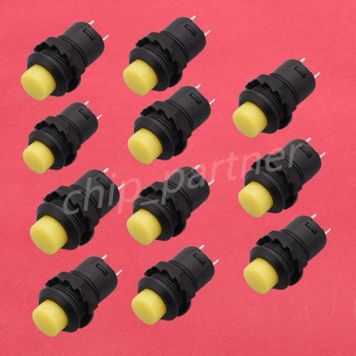
10pcs DS-228 DS-426 Yellow Self-locking Switch Normal Open NO 12mm Round Switch
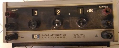
HP Hewlett Packard 4436A 600 OHMS DC-1MHZ 1W Test Set
Vintage Dosimeter CD V-746 Radiation Detector Pen - blue
By clicking "Accept All Cookies", you agree to the storing of cookies on your device to enhance site navigation, analyze site usage, and assist in our marketing efforts.
Accept All Cookies