


US $433.00
| Condition: |
New: A brand-new, unused, unopened, undamaged item in its original packaging (where packaging is
applicable). Packaging should be the same as what is found in a retail store, unless the item is handmade or was packaged by the manufacturer in non-retail packaging, such as an unprinted box or plastic bag. See the seller's listing for full details.
...
|
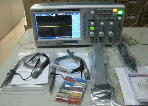
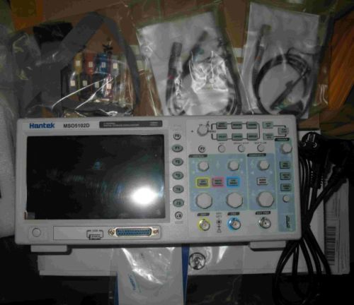
Model | MSO5102D |
| Channels | 2 | ||
| MPN | MSO5102D | ||
| Sample Rate | 1GSa/s - 1.9GSa/s | ||
| Type | Digital | ||
| Number of Channels | 2 | ||
| Bandwidth | 100MHz - 349MHz | ||
| Country of Manufacture | China |
Directions
Similar products from Logic Analysis Mainframe Systems
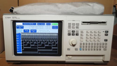
HP / Agilent 1670G Logic Analyzer Analysis System - Option 002 and 004
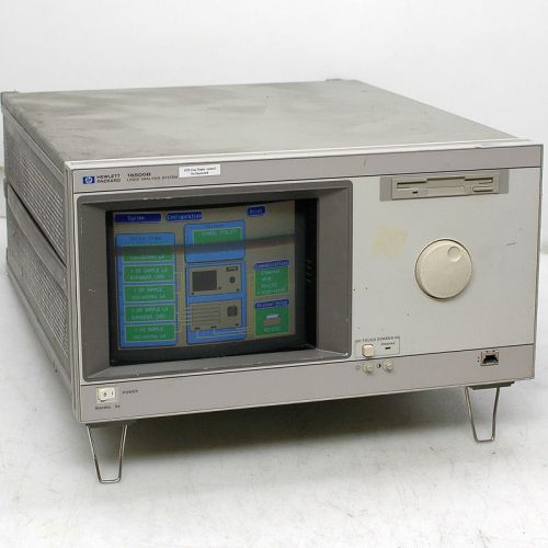
HP 16500 Logic Analyzer Mainframe +(5) 16556A 100MHz State/400MHz Timing Modules
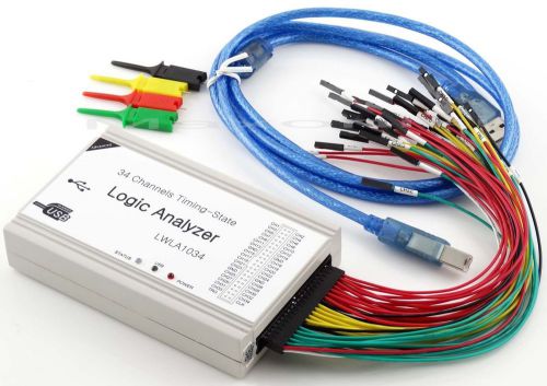
PC USB Logic Analyzer 34CH 100MHz 125MHz With Support I2C SPI UART PWM
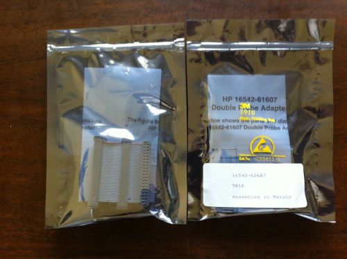
QTY-2 HP / Agilent 16542-61607 Logic Analyzer Double Probe Adapters, 40-pin
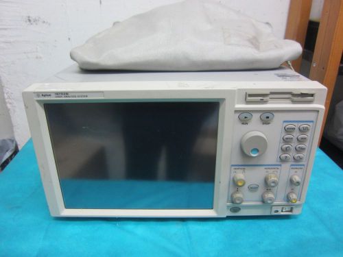
HP/AGILENT 16702B Logic Analysis System OPT. 003 W/ 16717A,16720A,16701
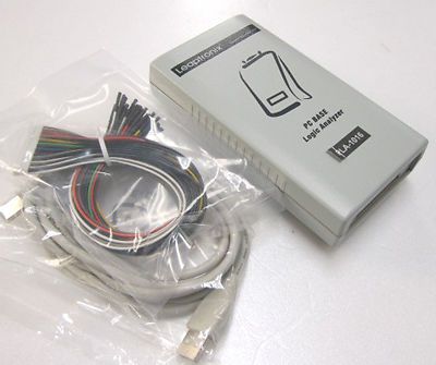
Logic Analyzer & Data Logger-PLA-1016
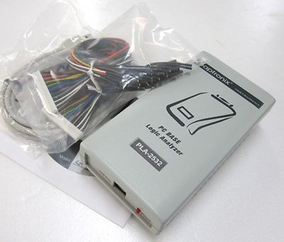
Logic Analyzer & Data Logger-PLA-2532
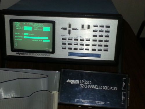
Arium ML4100B Logic Analyzer 100 MHz w/ LP32O 32 Channel LOGIC POD
HP / AGILENT 16500B LOGIC ANALYSIS SYSTEM W/ 16530A (BROKEN TOUCH SCREEN BUTTON)
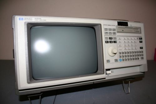
HP 1663A 34-Channel, 100MHz Portable Logic Analyzer For Parts, Repair
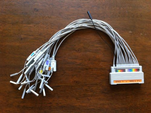
HP/Agilent E5383A - Pod 3 + L Clock Logic Analyzer Probe
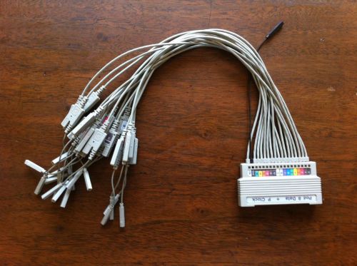
HP/Agilent E5383A - Pod 8 + P Clock Logic Analyzer Probe
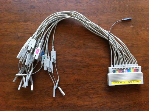
HP/Agilent E5383A - Pod 4 + M Clock Logic Analyzer Probe
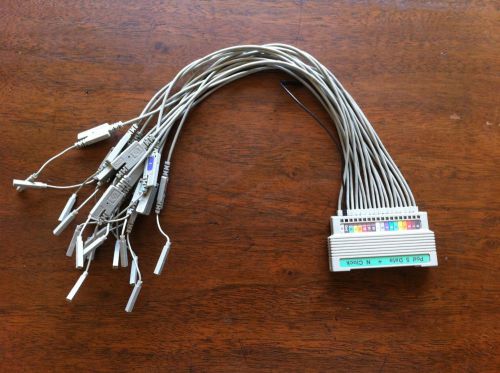
HP/Agilent E5383A - Pod 5 + N Clock Logic Analyzer Probe
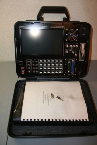
Ancot DSC-216/FXE SCSI Bus Analyzer
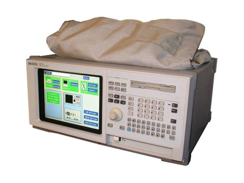
HEWLETT PACKARD HP / AGILENT LOGIC ANALYZER MODEL 1671E
HP 1664A Logic Analyzer, with test cable
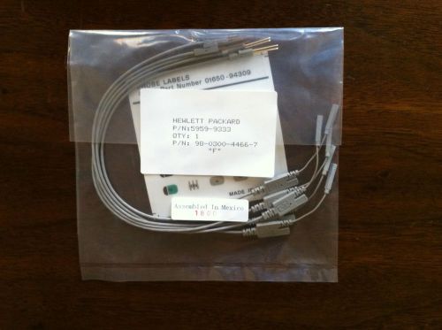
NEW HP / Agilent #5959-9333 Replacement Probe Leads for Logic Analyzer
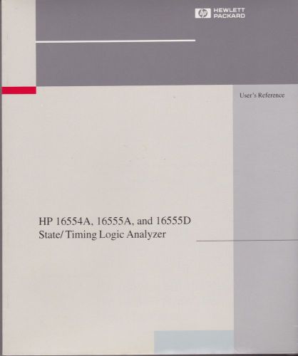
HP16554A, 16555A, 16555D Logic Analyzer Original Manual - Very Nice!
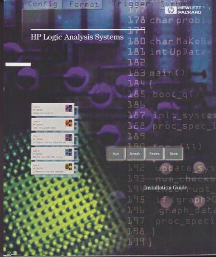
HP Logic Analyzer Original Installation Guide - Very Nice!
People who viewed this item also vieved
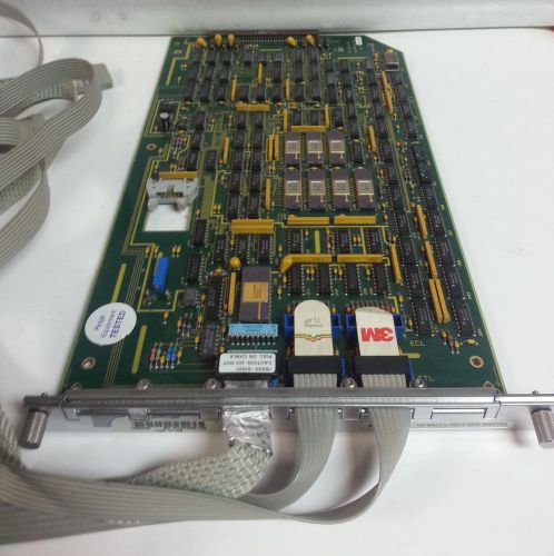
HP/Agilent 16760A logic analyzer module (AS-IS)
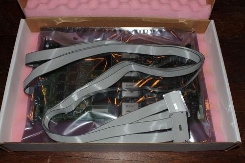
HP Agilent 16520A & 16541A Logic Analyzer Modules UNTESTED
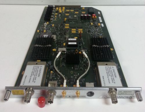
HP Agilent 16534A 2 Channel 500 MHz 2Gs/s Digitizing Oscilloscope Module TESTED!
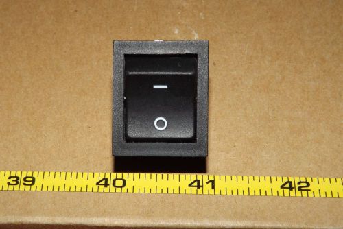
Perkin Elmer LS-50B OEM Part: C1350VA Power Supply Rocker Switch 1350/53
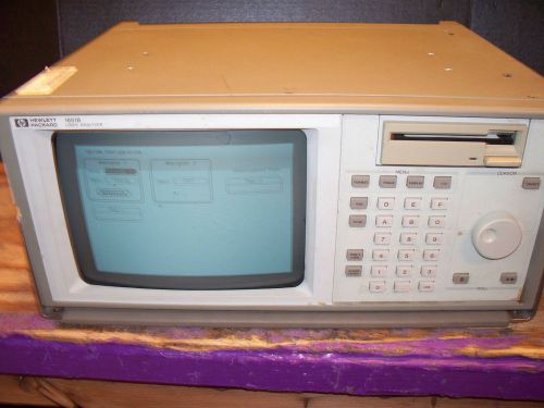
HP 1651B Logic Analyzer 32 Channel
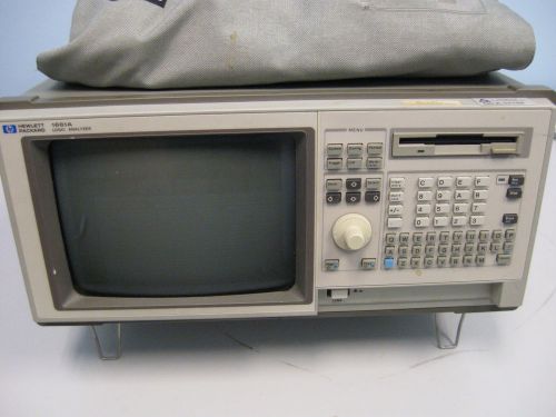
HP Logic Analyzer 1661A - 102 channels
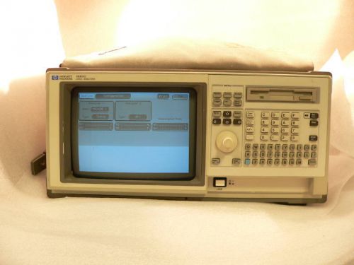
Hewlett Packard 1661C Logic Analyzer
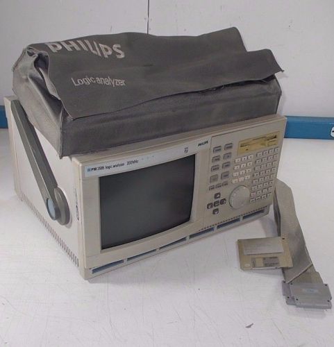
PHILIPS FLUKE PM3585/90 LOGIC ANALYZER 200 MHz FOR PARTS/REPAIR

Agilent 1691A 102Ch Portable Logic Analyzer PC Hosted
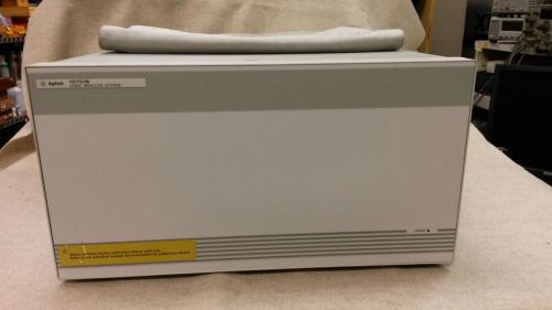
AGILENT 16701B LOGIC ANALYSIS SYSTEM EXPANSION FRAME
By clicking "Accept All Cookies", you agree to the storing of cookies on your device to enhance site navigation, analyze site usage, and assist in our marketing efforts.
Accept All Cookies