US $109.99
Directions
Similar products from Stepper Motor Driver Boards & Modules
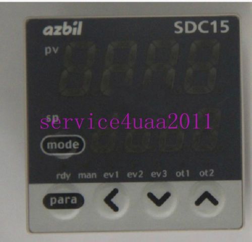
NEW Yamatake Thermostat C15MTR0TA0300 2 month warranty
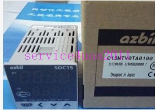
NEW Yamatake Thermostat C15MTV0TA0100 2 month warranty
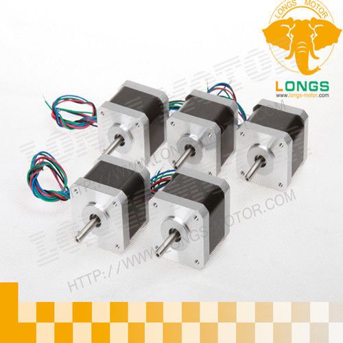
5pcs Nema 17 stepper motor 75oz.in 1.2A 4leads CNC 3D Printer Reprap
CNC controller Router nema23&34 425oz-in 878oz-in stepper Motor 5aaixs kit
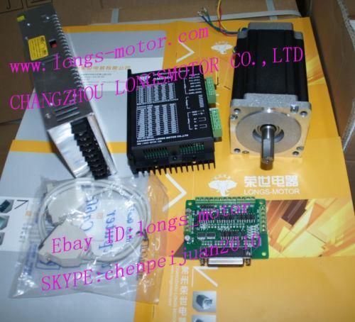
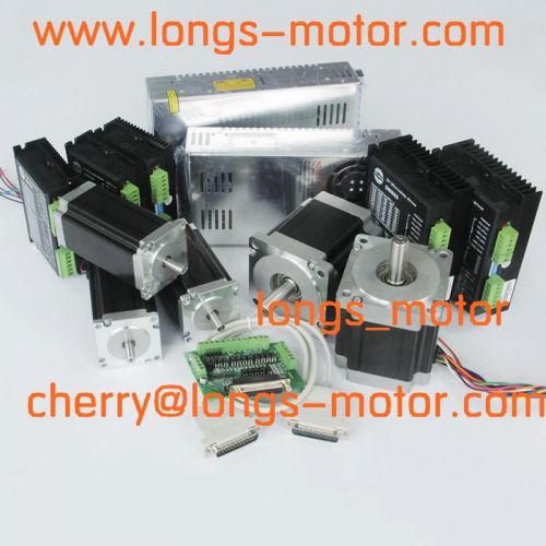
NEMA34 Stepper Motor1232oz-in CNC Driver DM860A 8.2A Power Longs Motor CNC MILL
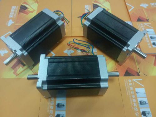
steppper motor NEMA34 1600oz 3.5A dual shaft high torque for cnc machinery route
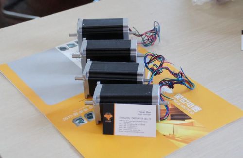
4pcs Nema23 dual shaft stepper motor 425oz.in CNC Router longs motor
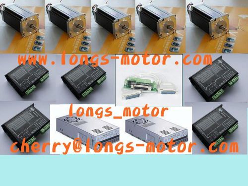
3Axis Nema34 Stepper Motor 8.5NM 6.0A &3pcs power CNC Router or Mill Longs Motor
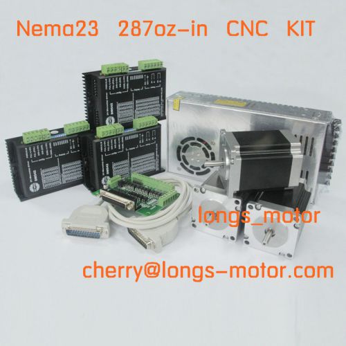
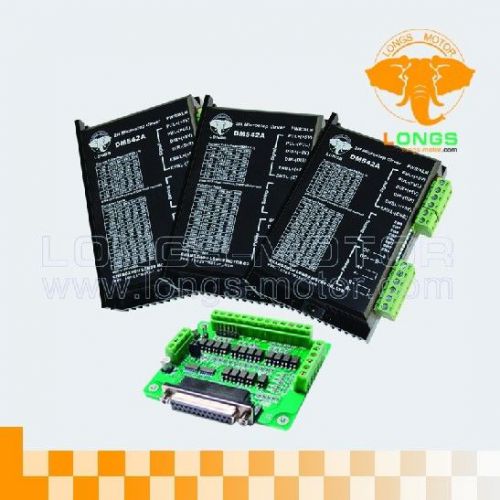
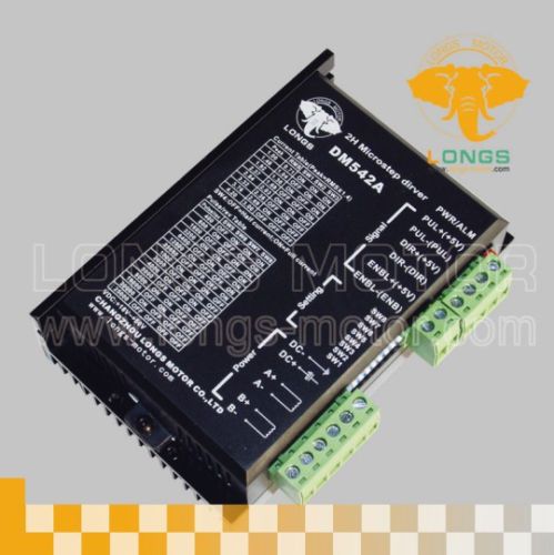
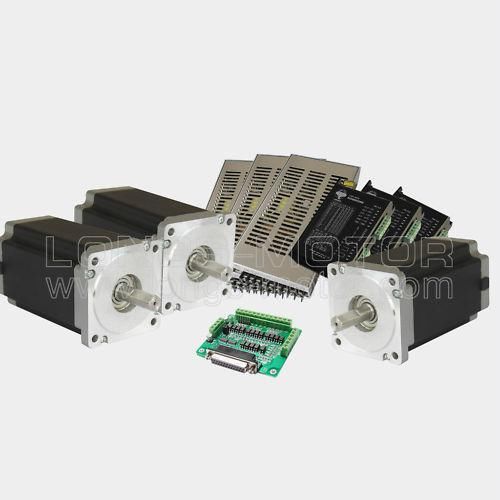
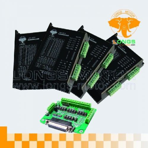
3AXIS Nema 23 Stepper Motor 287oz-in & Driver DM542A CNC Kit FREE SHIPPING
CNC Control 4Axis Stepper Driver,24-80VDC/7.8A/256Micro DM860A
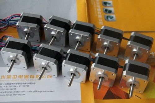
Nema17 stepper motor 55oz 1.7A 3D PRINTER, Robot, Reprap, Makerbot, Prusa 10pcs
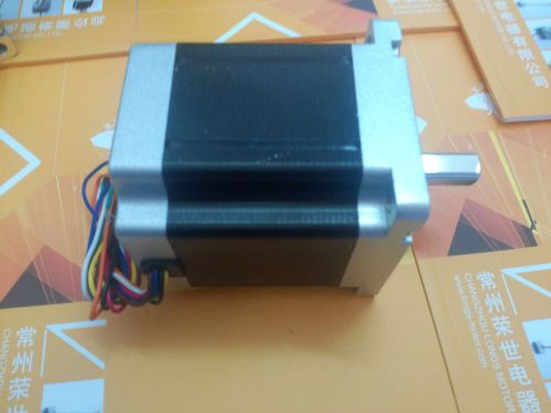
Nema34 Stepper Motor 880oz-in CNC Router/Mill 8leads new longs motor
Nema23 stepper motor 425oz & Driver DM542A 4.2A FOR CNC Router machinery 5axis
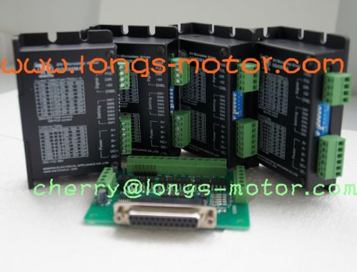
4Axis Stepper motor driver DM420A 1.7A 12-36VDC,128Micostep Bipolar CNC New
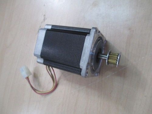
HP INDIGO CA244-02460 STP-58D5008 Stepper Motor
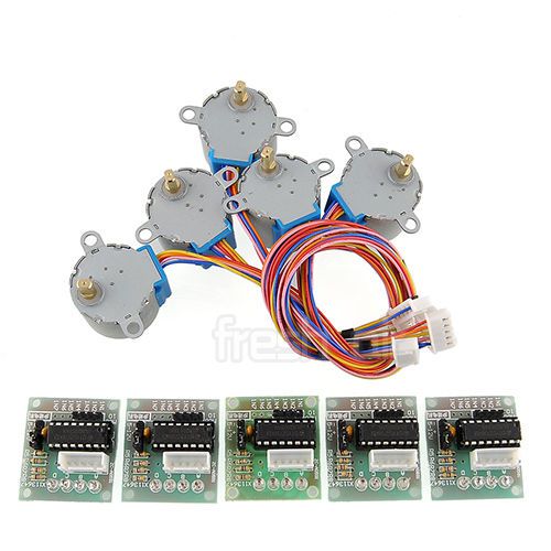
5X Stepper Motor 28BYJ-48 + ULN2003 Driver Test Module Board for Arduino
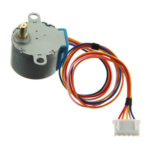
28BYJ-48 Gear Stepper Motor Moteur DC 5V 4Phase 5Wire Reduction Step For Arduino
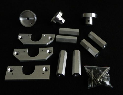
Proxxon MF70 CNC conversion kit for Nema 23 stepper motors
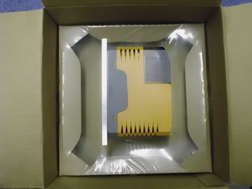
ACOPOSmicro 100D stepper 80SD100XD.C0XX-01
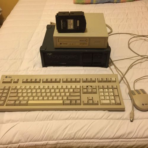
TADPOLE VOYAGER IIi SUN COMPATIBLE ULTRASPARC WORKSTATION COMPLETE
People who viewed this item also vieved
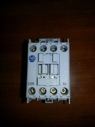
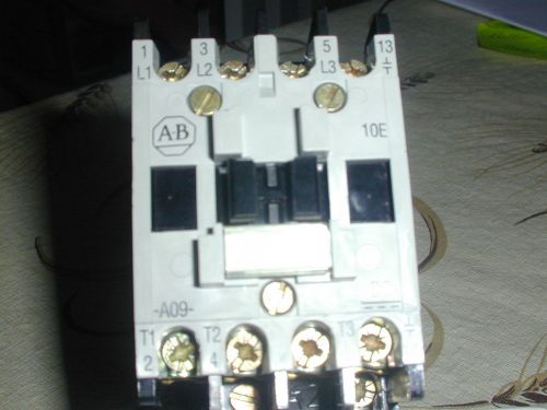
ALLEN-BRADLEY, CONTACTOR, SERIES A, 100-C09*10, 600 V, KW 3, MADE IN SWITERLAND
ALLEN BRADLEY BULLETIN 100 D.C. OPERATED CONTACTOR COIL 24V 714
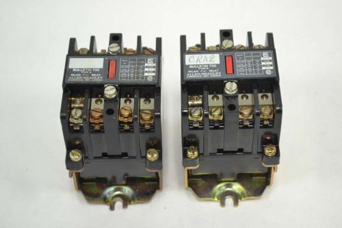
LOT 2 ALLEN BRADLEY 700N RELAY 120-300V-AC 60A AMP 7200VA B359136
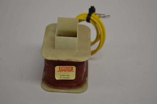
NEW DECCO 9-2582 COIL REPLACEMENT PARTS 115V-AC CONTACTOR D359115
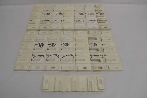
LOT 15 NEW WESTINGHOUSE 112D114H01 HORIZONTAL BUS INSULATOR D359079
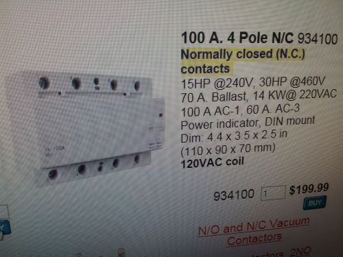
electrodepot lighting contactor 100 A. 4 pole 240 V 120 A. at the coil
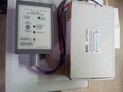
INSTEON 240V 30 AMP LOAD CONTROLLER C DUAL BAND
TEXAS INSTRUMENTS MODEL 500-2151 POWER SUPPLY
GE Switchgear Bus Bar Shunt 6000A=100mV 50-140024UP AA
Allen-Bradley 199-FSMA9 Ser.B 24-48V Surge Suppressor Used Lot of(4)
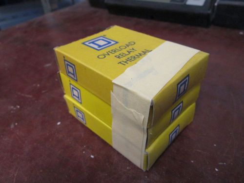
Square D Overload Relay Thermal Unit AR-9.3 *Lot of 3* Used
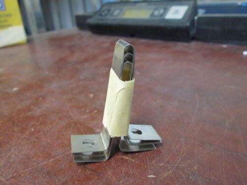
Square D Overload Relay Thermal Unit AR-17.6 *Lot of 3* Used
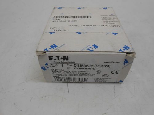
NEW EATON DILM32-01 POWER CONTACTOR 3POLE 15KW/400V, AC
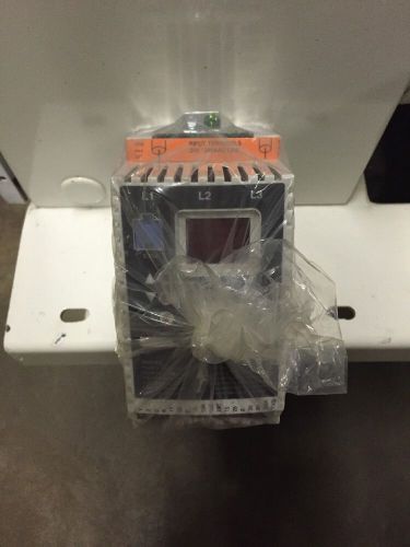
AC TECH ADJUSTABLE SPPED AC MOTOR CONTROL SF230
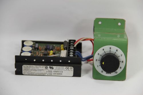
Dart Controls 125DV-C-K Speed Control DC Variable 120/240 VAC
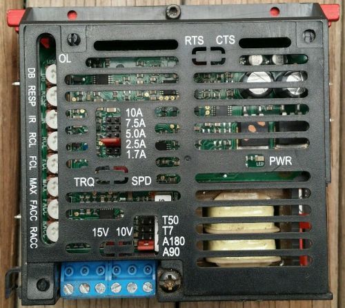
GOOD USED DAEDAL MD SERIES 3 DRIVER FOR CNC APPS. MORE - FROM FUNCTIONING SOURCE
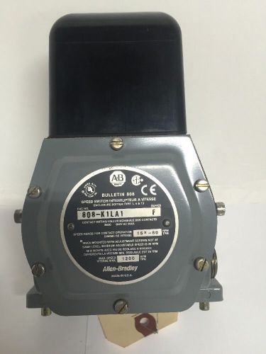
ALLEN BRADLEY 808 SPEED SWITCH LOW SPEED N.C.
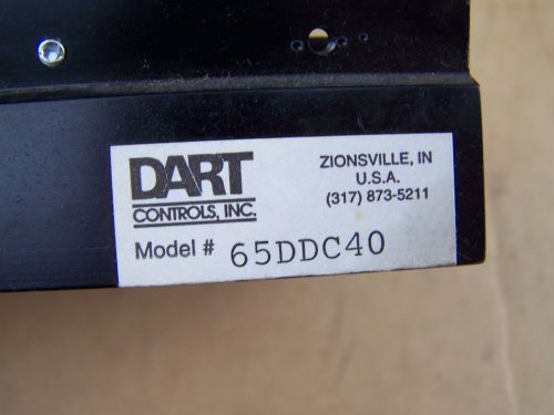
Dart Battery DC Motor controller PN 65DDC40 With 1/8 Hp Honeywell motor-30VDC
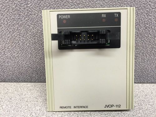
YASKAWA JVOP-112 REMOTE INTERFACE
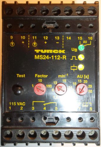
TURCK MS24-112-R MULTI SAFE RELAY MS24112R
By clicking "Accept All Cookies", you agree to the storing of cookies on your device to enhance site navigation, analyze site usage, and assist in our marketing efforts.
Accept All Cookies