US $1300
Directions
Similar products from Sound Pressure Testers & Sound Level Meters
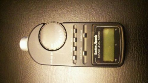
Radio shack db sound level meter
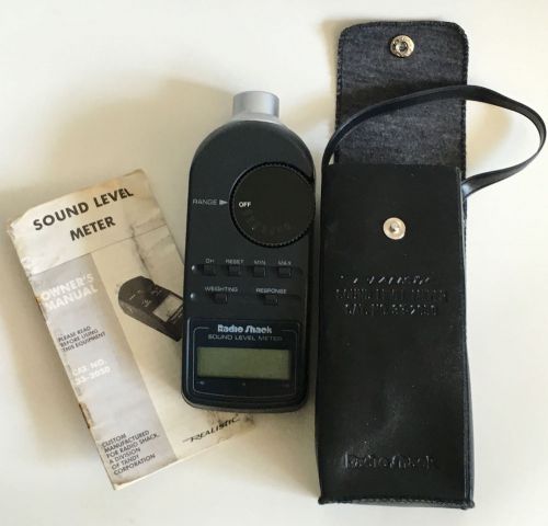
Radio Shack Realistic Sound Level Meter
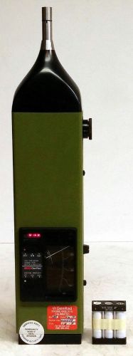
GENERAL RADIO GENRAD 1982 PRECISION LEVEL SOUND METER & ANALYZER
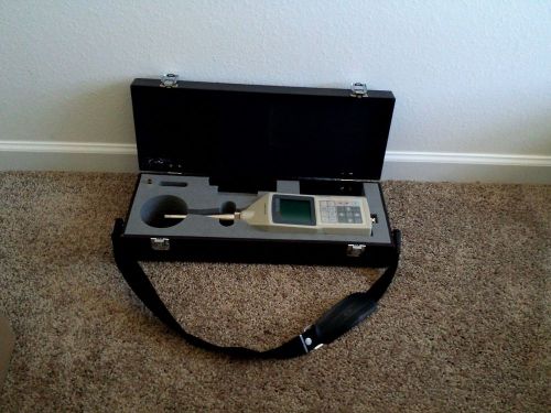
USA SELLER Ono Sokki Precision Integrating Sound Level Meter LA-500 w/ hard case
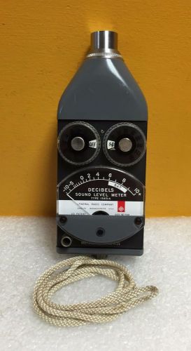
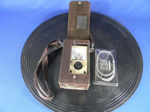
General Radio (GR) 1565-A, 44 to 140 dB, Sound Level Meter + Case & Microphone
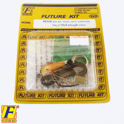
Basic Simple mini AM RADIO EARPHONE 3VDC STUDENT ELECT CIRCUIT BOARD UN ASSEMBL
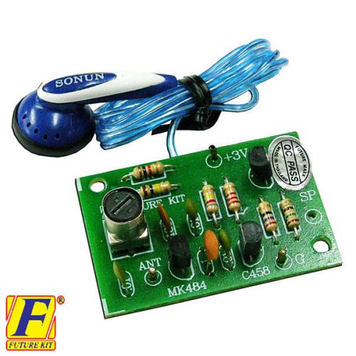
EARPHONE 3VDC Simple Basic MINI AM RADIO electrical circuit board kit DIY
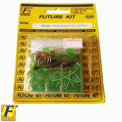
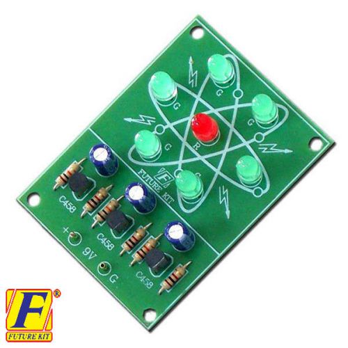
ATOMIC CHASING LIGHT 7 LED STUDENT ELECTRONIC LEARNING CIRCUIT BOARD UN AS
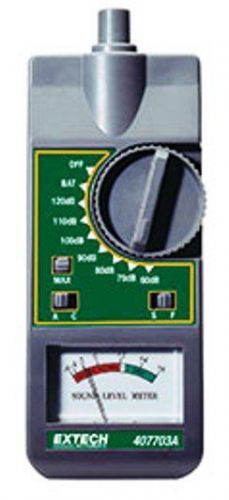
EXTECH ANALOG SOUND LEVEL METER 407703 NEW
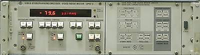
Rohde & Schwarz UPSF2 video noise meter
Cirrus CRL221C Type 2 Sound Level Meter
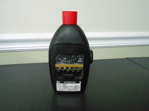
GenRad Permissable Sound Level Meter 1565-B
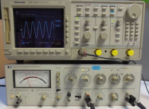
HP/Agilent 339A Distortion Measurement Test Set
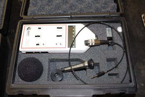
Quest Model 2700 Impulse Sound Level Meter
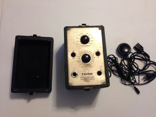
Vintage TRIMM Audiometer Black
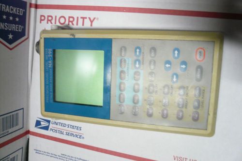
RION precision sound level meter na-29e AS IS ..READ AD
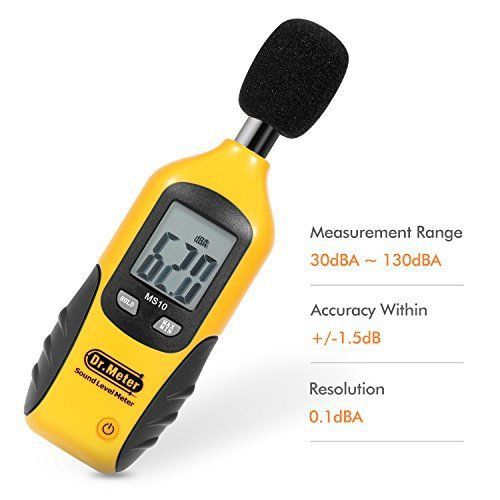
Dr.Meter MS10 Digital Decibel Sound Level Meter Tester 30 dBA - 130 Measurement
People who viewed this item also vieved
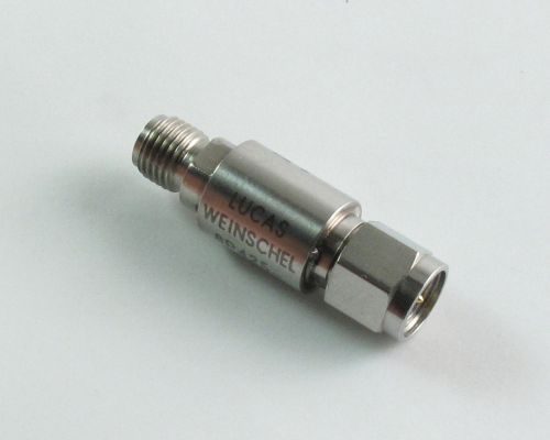
Lucas Weinschel 8P425-011S-001 ¦ 5731-4.0 ¦ SMA Attenuator
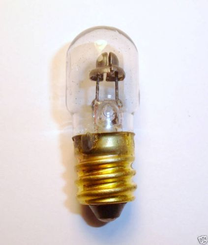
AMERICAN Made by *GE NE-45 B7A Shorts Indictor Hickok Tester Lamp Bulb Free Ship
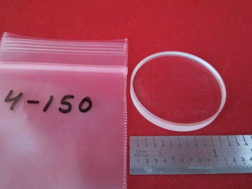
OPTICAL LENS LASER OPTICS #4-150 BIN#4
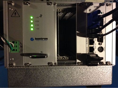
Used Kontron 3U CPCI / CompactPCI Chassis / with CP306 CPU System Controller
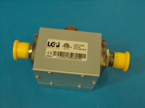
LGP TELECOM LGP11220 CURRENT INJECTOR, OUTDOOR, CIN OD 1710-1880 MHz
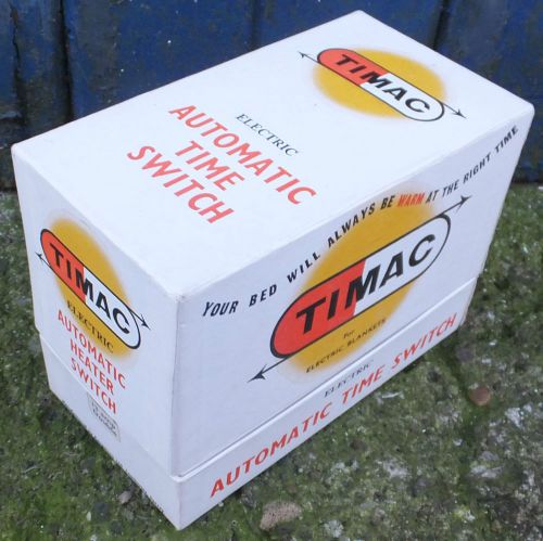
Vintage boxed retro Timac Electronic Automatic time switch looks unused
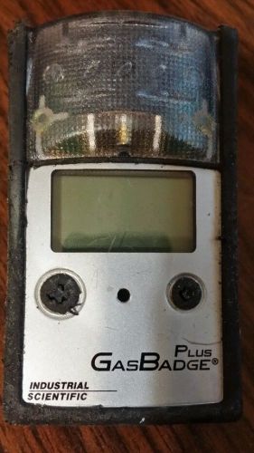
Industrial scientific h2s gas badge plus dead
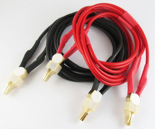
1pair 1M 3.3FT Double Gold-plated Copper Kelvin Clip 4 wires Silicon Test Cable
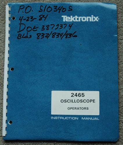
Tektronix 2465 Osciolloscope Original Operators Manual, Great conditio
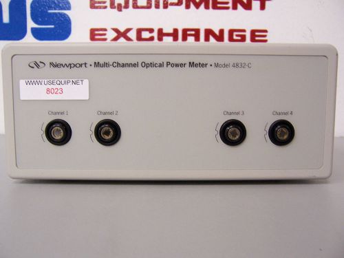
8023 NEWPORT 4832-C MULTI-CHANNEL OPTICAL POWER METER
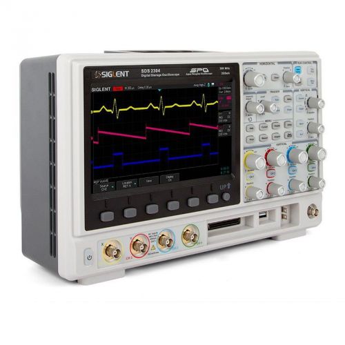
SIGLENT SDS2304 Digital Oscilloscope
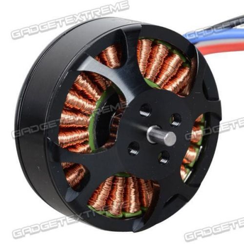
Sunnysky X4108S 600KV Brushless Disc Motor for Quadcopter Multicopter G
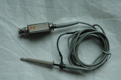
HP Agilent 10018A 10X Mini Scope Passive Probe, with Hock, Ground Clip
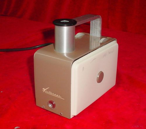
Victoreen Radiation Condenser R-Meter X-Ray Meter Model 570
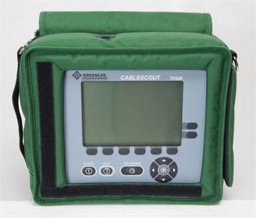
Greenlee TV220 CableScout - TDR Cable Tester for CATV
Vintage FREAS GLASS LAB THERMOMETER
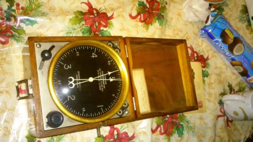
Extremely Rare General Radio co Synchronometer,
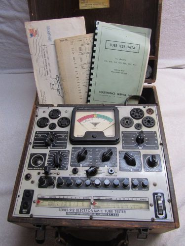
Precision Tube Tester Model 512 - Wood Case
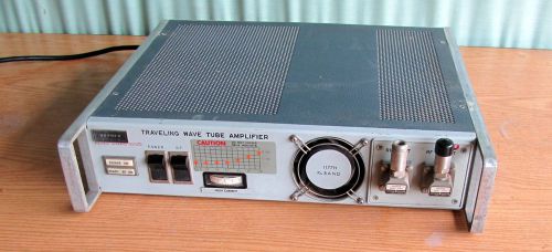
Hughes 1177H04F000 TWT Amplifier, S# 180, 12.4 - 18.0 GHz. 120 VAC 10 W
By clicking "Accept All Cookies", you agree to the storing of cookies on your device to enhance site navigation, analyze site usage, and assist in our marketing efforts.
Accept All Cookies