US $5,495.00
| Condition: |
Seller refurbished: An item that has been restored to working order by the eBay seller or a third party not approved by
the manufacturer. This means the item has been inspected, cleaned, and repaired to full working order and is in excellent condition. This item may or may not be in original packaging. See the seller’s listing for full details.
...
|
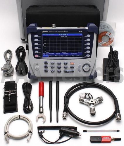
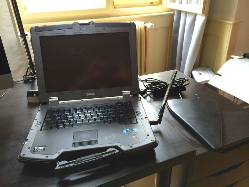
Brand | JDSU |
| Model | JD724C |
Directions
Similar products from Cellular Test Sets and Antenna Analyzers
ANRITSU MS2724B, HAND-HELD SPECTRUM AN; 9kHz TO 20 GHZ
ANRITSU MW8208A 850 MHz PIM Master
ANRITSU S820D Accessory Kit SITEMASTER ACCY KIT
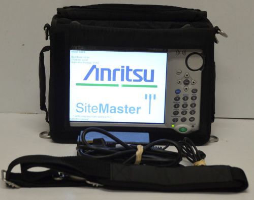
Anritsu S331E SiteMaster Cable/Antenna Analyzer
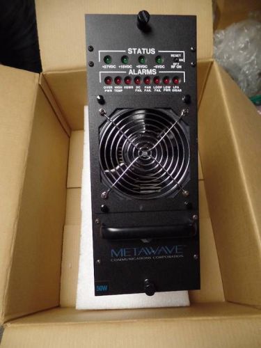
POWERWAVE MCA9107-50 METAWAVE 275-0003 POWER SUPPLY NEW
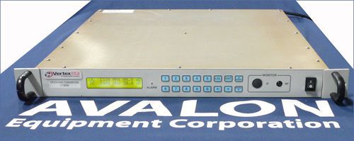
Vertex RSI LT-3000 LT3000 Integrated L-Band Up/Down Converter
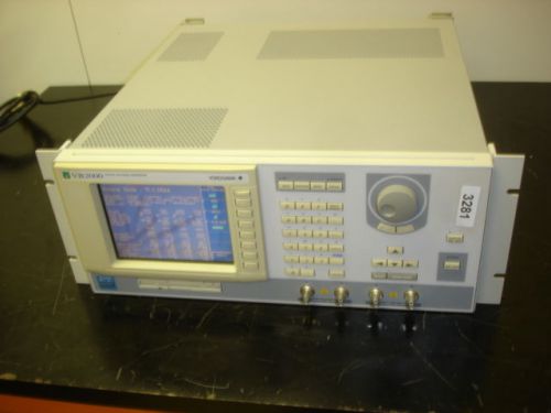
YOKOGAWA VB2000 Wide-Band BaseBand IQ Signal Generator # 3281
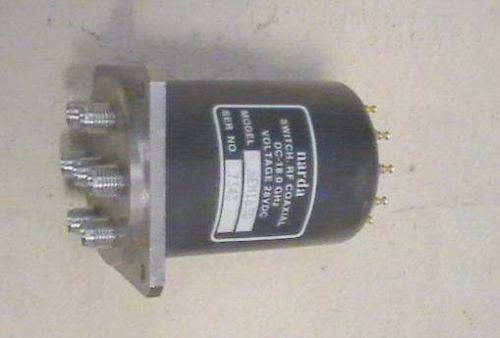
Narda RF Coaxial Switch SEM163d DC-18.0GHz
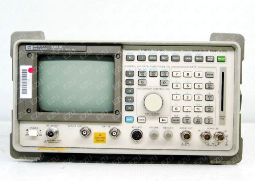
Agilent 8921A RF Cell Site Test Set (Commumication Test Set)
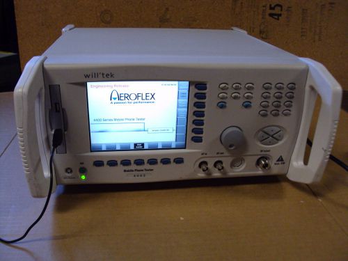
Willtek - Aeroflex 4403 Multi-system Mobile Phone Tester Options M 101 105 CDMA
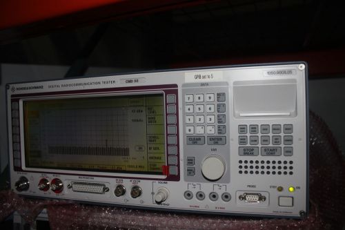
Rohde Schwarz CMD55 CMD-55 Radio Communications Tester / 1050.9008.05 options NR
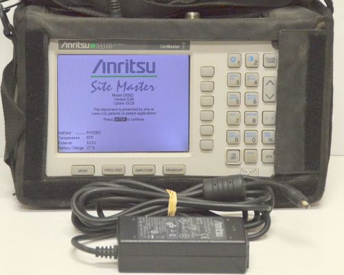
Anritsu S331D SiteMaster Cable & Antenna Site Master w/ Options 3 & 29
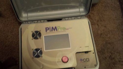
PimPro 1921 Precision Passive Intermod Analyzer
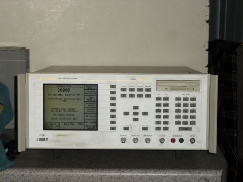
Wavetek 3600D Cellular Test System Cell Phone Test System
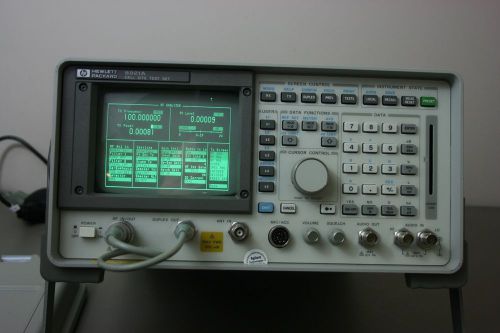
HP Agilent 8921A Radio Service Monitor, Calibrated with 30 day Warranty
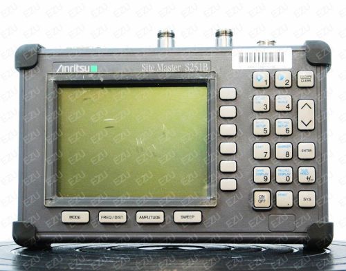
Anritsu S251B - 05 Site Master Cable and Antenna Analyzer
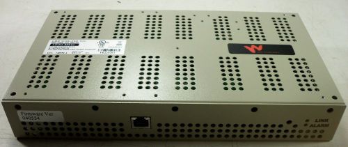
LGC Wireless 1900 MHz UNS-PCS-2 EPN: 740552-4 Unused
AGILENT E7475A SYS OPT 310 E6451A DIGITAL RECIVER GPS 880-915/925-960 MHZ
Best Spectran HF-XFR AAronia Spectrum Analyzer
People who viewed this item also vieved
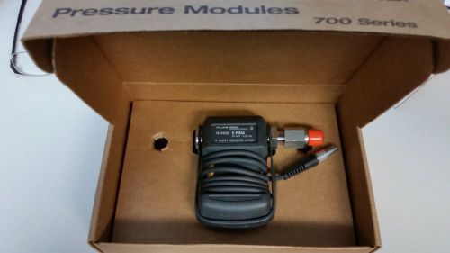
FLUKE 700PA3 0-5 PSIA Absolute Vacuum Pressure Module Used Once
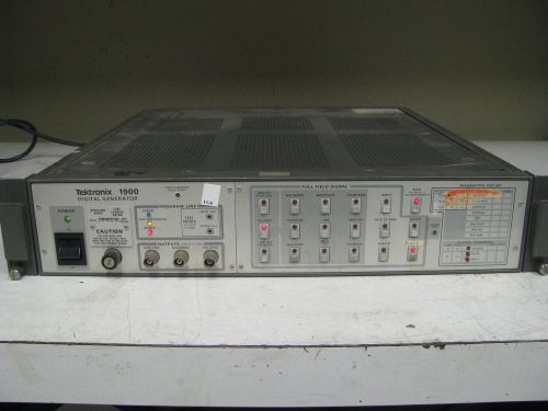
Tektronix 1900 10 Bit NTSC Test Signal Digital Generator FG6
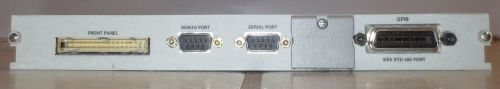
CPU Module 671-2581-11 / 671-2581-11 for Tektronix HFS9009
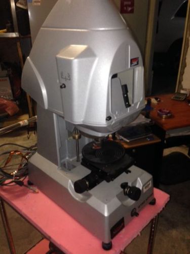
Veeco Wyko NT1100 Optical Profiling System
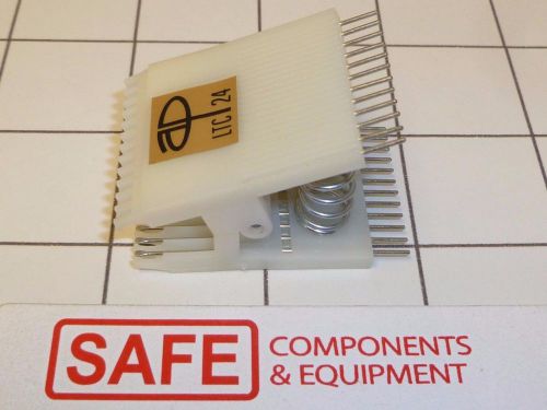
3M A/P LTC20 + LTC24 + TC40 ICTest Clips DIP Special Offer E31
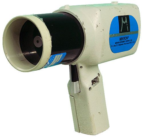
Mikron Instrument 80A2-CH Range Thermometer
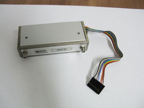
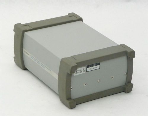
HP Agilent 33321SC Programmable Step attenuator
Hobbs LR 42455 Elapsed Time Indicator
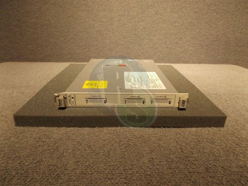
Racal 1260-16 40 Channel SPDT Relay Actuator VXI Module 407348-S-1437
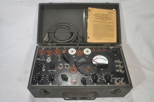
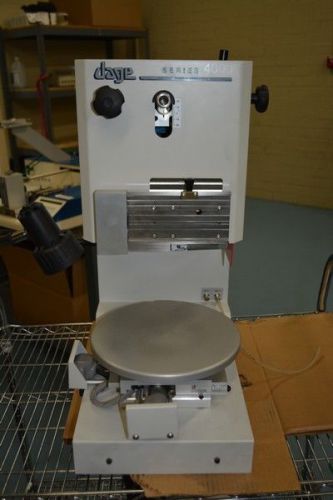
(1) DAVEN tube tester, I-177-B for parts or restoration
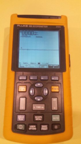
Fluke 123 Scopemeter With Current Probe
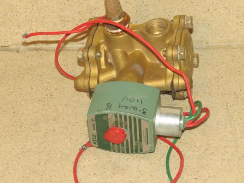
ASCA RED-HAT VALVE ACCESSORIES CAT NO 8316G24 (HI)
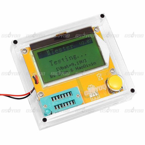
Mega328 Transistor Tester ESR Meter LED Diode Triode Capacitor w/ Clear Case Hot
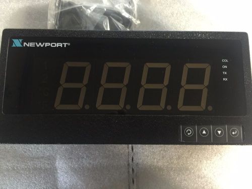
NEWPORT ELECTRONICS ILD24-EI/N,FS MULTIFUNCTION METER New
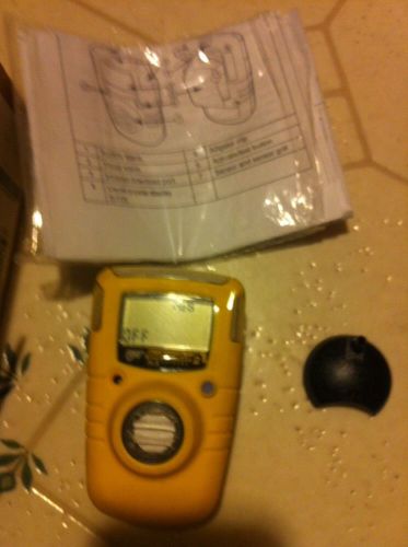
Honeywell BW Tech. Gas Alert Clip Extreme 113604
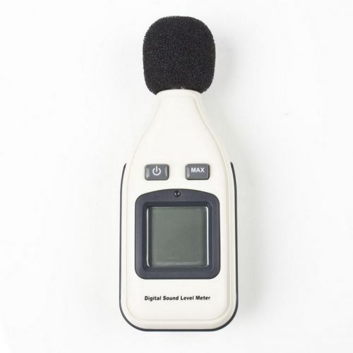
Digital sound level meter Large LCD screen SC2
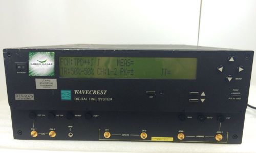
Wavecrest DTS-2075 Time Measurement Instrument (Digital Time Scope)
TTC/Acterna 4000 Communications Analyzer Communications Analyzer
By clicking "Accept All Cookies", you agree to the storing of cookies on your device to enhance site navigation, analyze site usage, and assist in our marketing efforts.
Accept All Cookies