

US $12.50
| Condition: |
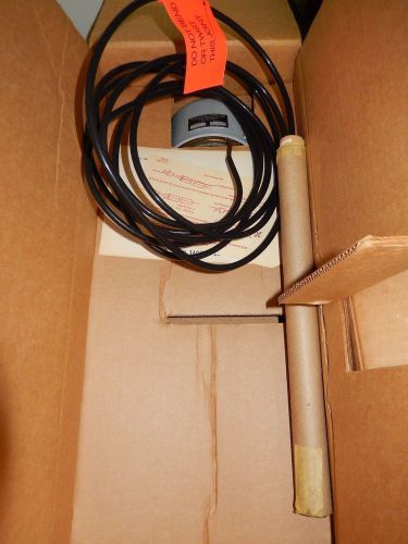
Used: An item that has been used previously. The item may have some signs of cosmetic wear, but is fully
operational and functions as intended. This item may be a floor model or store return that has been used. See the seller’s listing for full details and description of any imperfections.
...
|
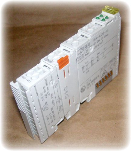
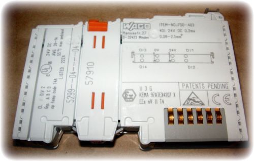
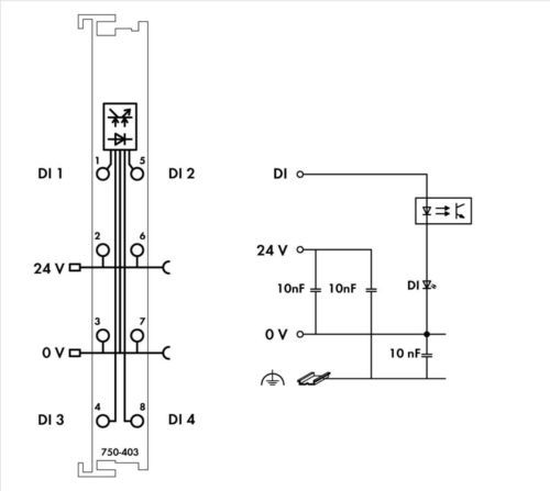
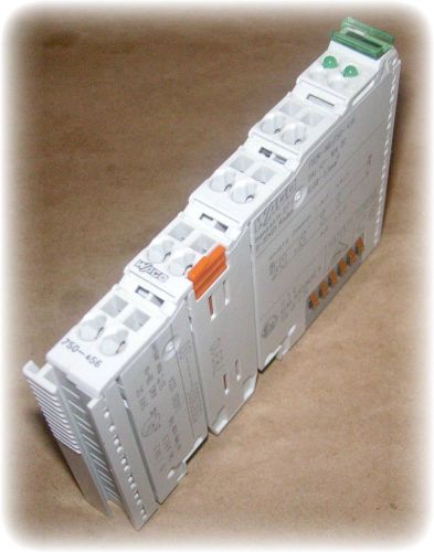
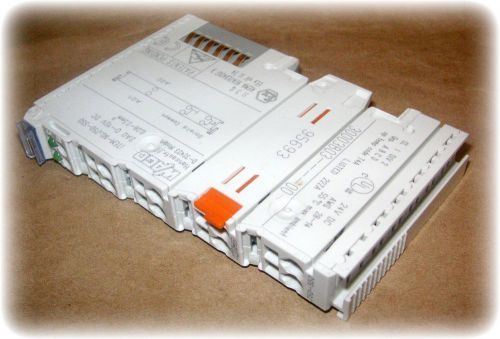
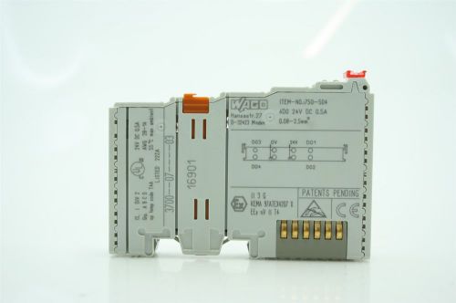
Brand | Wago |
| Country/Region of Manufacture | Germany | ||
| MPN | 750-403 | ||
| EAN | 4045454424732 |
Directions
Similar products from Web Servers, Ethernet Relay Boards, Ethernet Adapters & Switches
Beckhoff EP2318-0001 EtherCAT compact box 8 channel digital combi M8
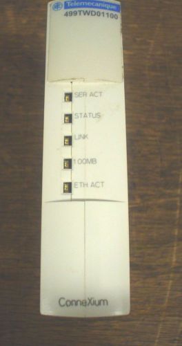
Used Telemecanique connexium ethernet interface 499TWD01100 -60 day warranty

Advantech EDG-6528L 8-Port Industrial Unmana GED Switch Rev:A1
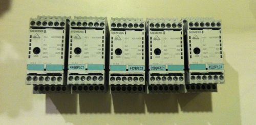
LOT OF (5) SIEMENS AS-INTERFACE MODULE 3RK2400-1FE00-0AA2
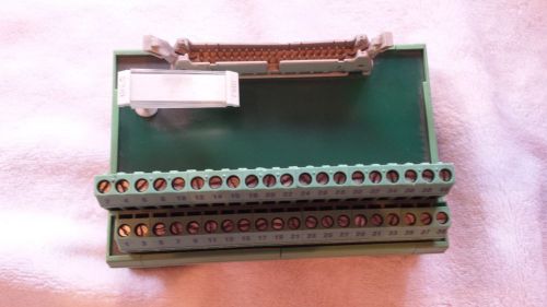
PHOENIX CONTACT FLKM40 VARIOFACE MODULE 2281076 USED
Module, Input, Analog, 2-Channel, ±10V Differential Inputs (Wago #750-456)
Module, Output, Analog, 2-Channel, 0-10V, I/O System 750 (Wago #750-550)
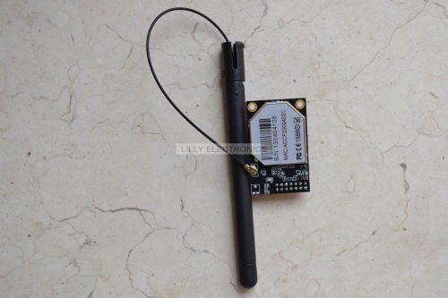
USR-WIFI232-B SERIAL TTL RS232 TO 802.11 B/G/N CONVERTER EMBEDDED WIFI MODULE
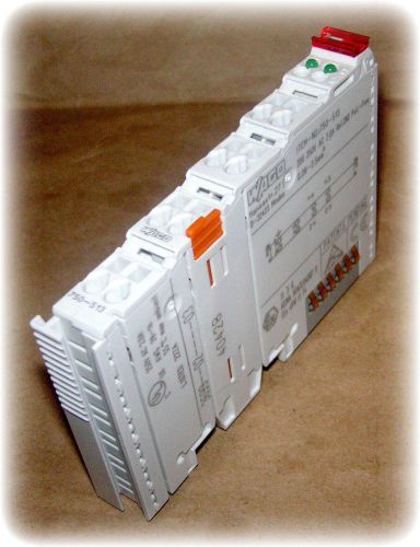
Module, Output, 2 Channel, Relay 2 NO, 230 VAC, 30 VDC, (Wago #750-513)
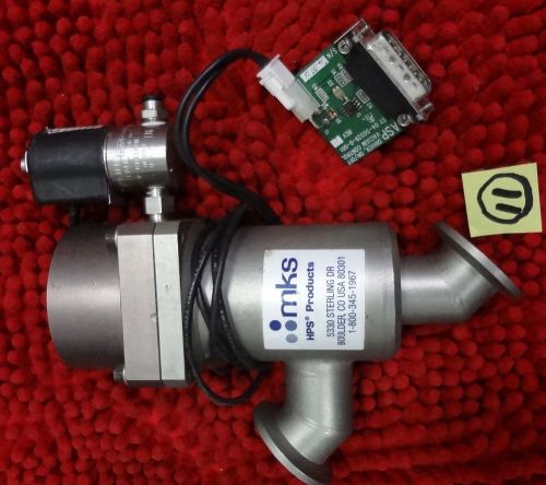
MKS 28-50390-001 Inline Vacuum Control Valve W/ Peter Paul 12V Valve

BRAD HARRISON BTY812P-FBP-003 MULTI-PORT INTERCONNECT SYSTEM, NEW*
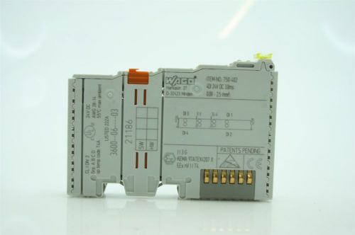
WAGO 750-402 4DI 24Vdc 3.0ms - Industrial I/O
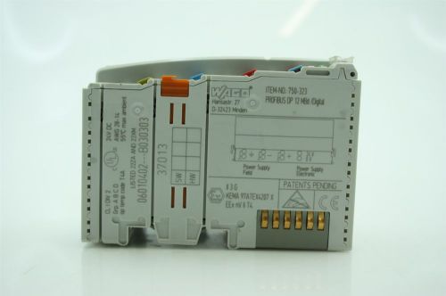
WAGO 750-323 PROFIBUS DP 12 MBd /Digital - Industrial I/O Master Unit + PLUG
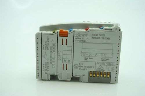
WAGO 750-303 PROFIBUS / FMS 12 MBd - Industrial I/O Master Unit
WAGO 750-504 4DO 24Vdc/0.5A - Industrial I/O
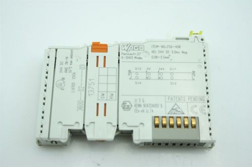
WAGO 750-408 4DI 24Vdc 3.0ms Neg.- Industrial I/O
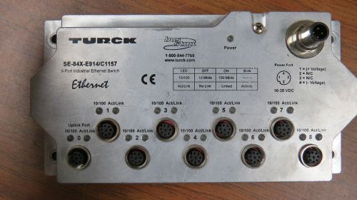
Turck SE-84X-E914 / C1157 Industrial Ethernet Switch 9 Port A80
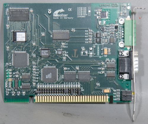
Hilscher CIF 30-DNM DeviceNet-Master Communication Interface ISA CIF30

Beckhoff Devicenet Compact Box Digital Input 8 Channel IP1011-B520 NEW
People who viewed this item also vieved
NEW Powers #11 Thermal System 700-T15JI05
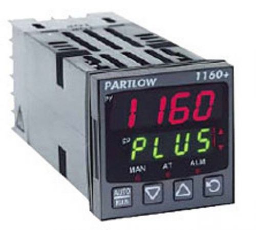
NEW IN BOX Partlow P1160110000 Single Loop Electronic Controller
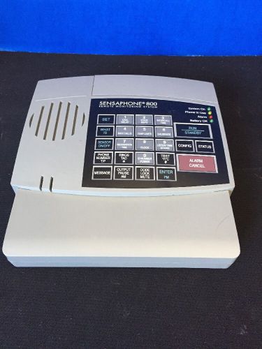
Sensaphone FGD-800 8 Zone Alarm Dialer
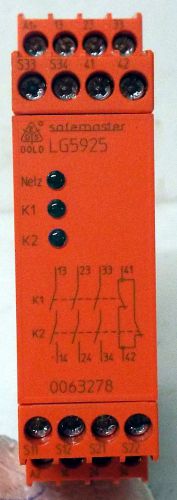
1 USED DOLD&SOHNE LG5925.48/900/61 LIGHT BARRIER CONTROLLER
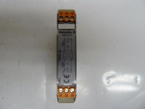
WEIDMULLER WASS CCC LP SIGNAL PASSIVE ISOLATOR 844495
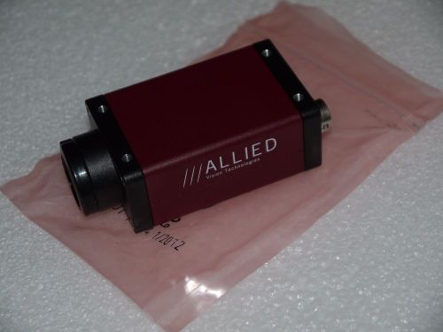
NEW ALLIED VISION TECHNOLOGIES MANTA G-201B ASG 30FPS MONOCHROME CCD CAMERA
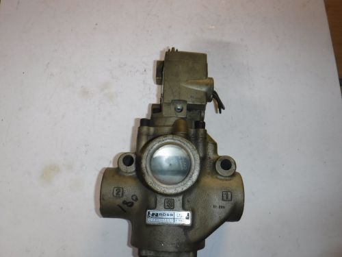
ROSS SOLENOID VALVE 1" 110V 2773B6001
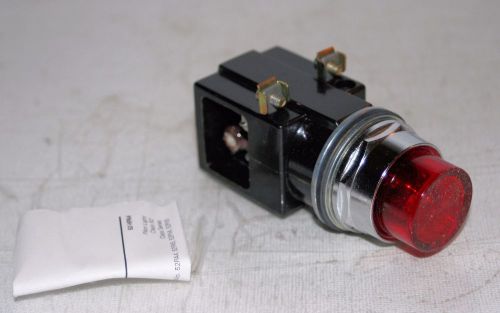
OIL TIGHT PILOT LIGHT 240V RESISTOR SIEMENS / FURNAS 52PA4N2
MOTOR STARTER SWITCH 1HP 1POLE 115/230V NEMA1 GENERAL ELECTRIC CR101-Y11
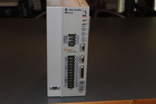
Allen-Bradley Ultra 3000 mo. 2098DSDHV030SE Industrial Control System
Allen Bradley, SLC 500, 1746-P2, SER C, Power Supply MFD2007

Allen Bradley AB 2711-K5A2 PanelView 550 Operator Terminal, FRN 4.10
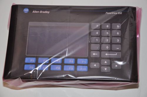
Allen Bradley AB 2711-K5A2 PanelView 550 Operator Terminal, FRN 4.00
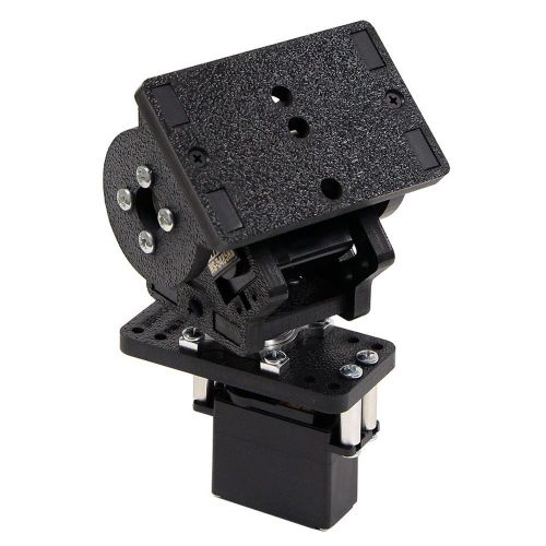
Actobotics SPT200 Pan and Tilt Kit
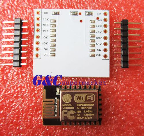
ESP-12E ESP8266 e Serial Port WIFI Module with IO Adapter Plate Expansion M95
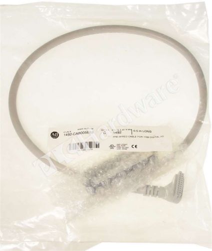
New Allen Bradley 1492-CAB005E69 /C Prewired Cable for 1769-OB16 and -OV16 0.5m

New Allen Bradley 1492-CAB005B69 /C Prewired Cable for 1769-IQ16 and -IQ16F 0.5m
By clicking "Accept All Cookies", you agree to the storing of cookies on your device to enhance site navigation, analyze site usage, and assist in our marketing efforts.
Accept All Cookies