US $90.00
Directions
Similar products from Stepper Motor Driver Boards & Modules
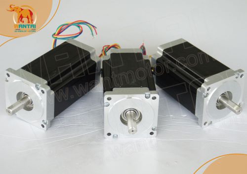
USAfree nema23 wantai motor with 3N.M(270OZ-IN),DIY,CNC,FAST,Best quality,cnc
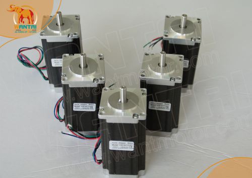
Single shaft stepping motor nema 23 with 425oz-in 4.2A for cnc machine,UPS ship
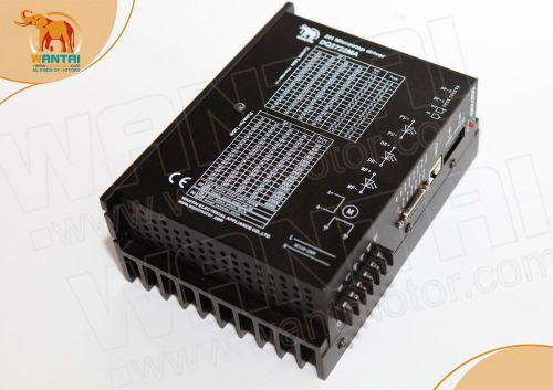
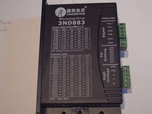
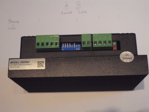
Driver DQ2722MA replace DM2722A 110-230VAC 2Phase 7A 300Micro for nema42
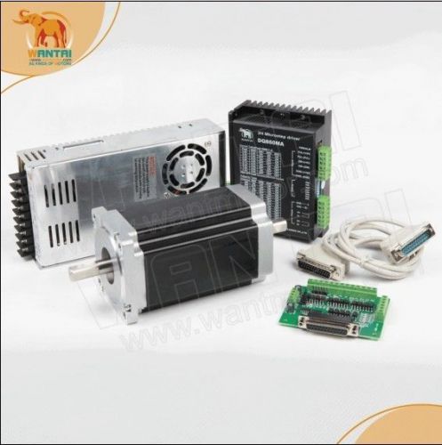
Wantai 1 Axis Nema34 Stepper Motor Dual Shaft 1600oz-in 12N.m CNC Kit&MACHINE
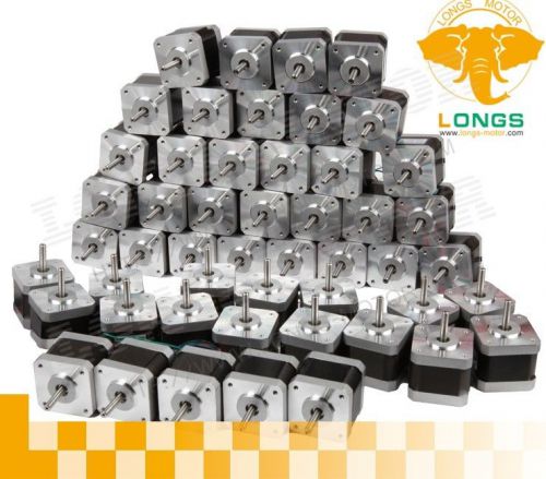
US&EU FREE SHIP-60PCS 3D PRINTER Nema17 ,1.7A,4000g.cm,STEPPER MOTOR 17HS4401N
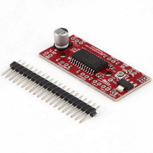
EasyDriver Shield stepping Stepper Motor Driver V44 A3967 For Arduino LO
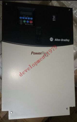
NEW AB AC Drive 22C-D072A103 ( 22CD072A103 )
CNC Router 1 Axis Controller Stepper Motor Drivers TB6560 3A driver board YF
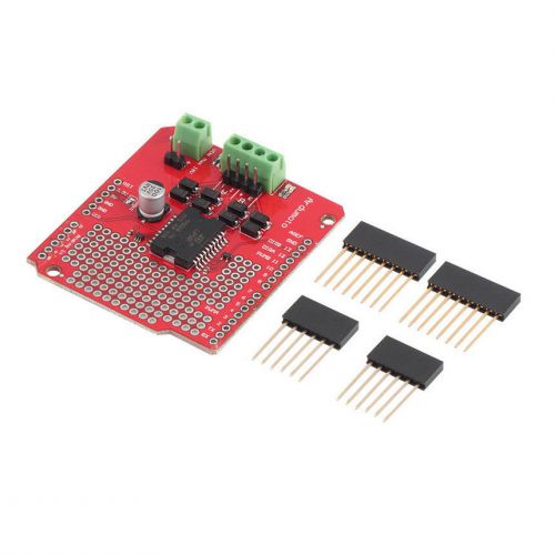
Dual Channel Motor Driver Shield L298P DC Stepper Driver Board For Arduino SC
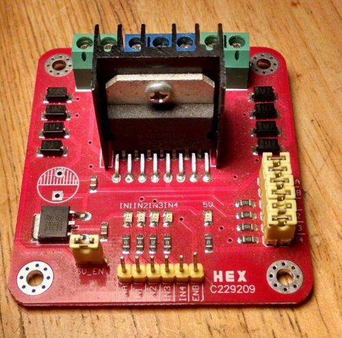
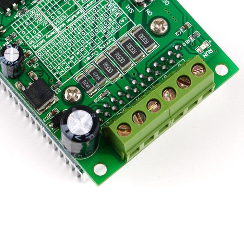
Hex C229209 stepper motor driver using L298N chip
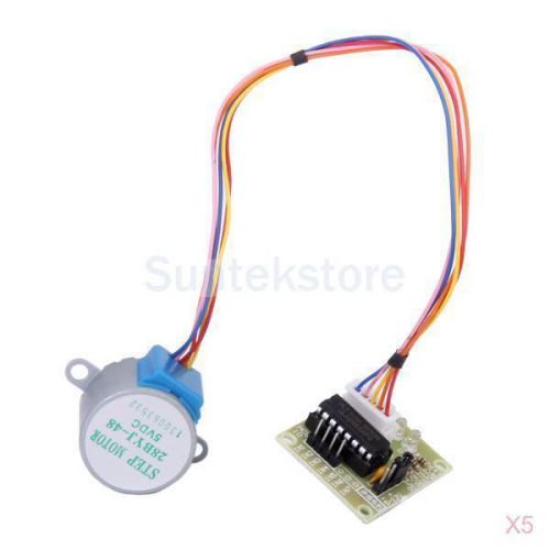
5x DC5V Stepper Motor 28BYJ-48 5 Line 4 Phase + Drive Test Module Board ULN2003
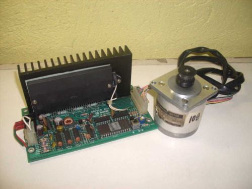
Servo KY56LM1-016 KY56LM1016 Stepping Motor w/ Driver Board
CNC 3rd Generation Revolutionary & Professional 4 Axis TB6560 Stepper Driver Set
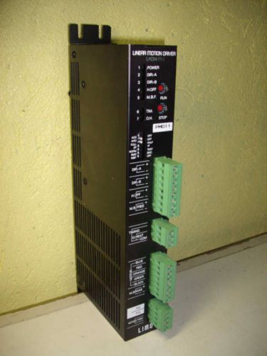
Oriental Motor LKD14-M-1 LKD14M1 Linear Motion Driver
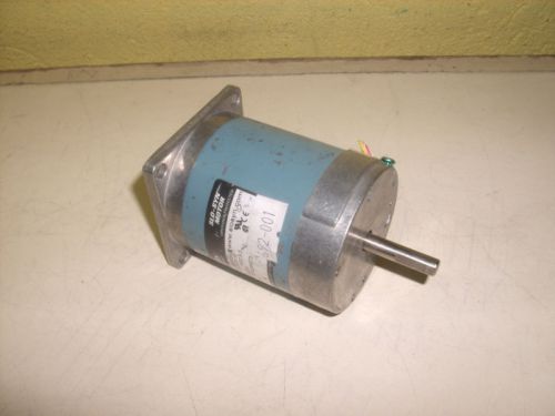
Superior Electric M062-LE-511E M062LE511E Step Motor 5.3VDC 1.6A
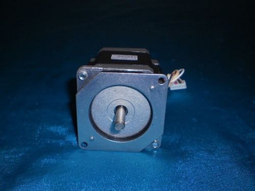
Shinano Kenshi STP-58D3022 14900G STP58D3022 1.8 Stepping Motor
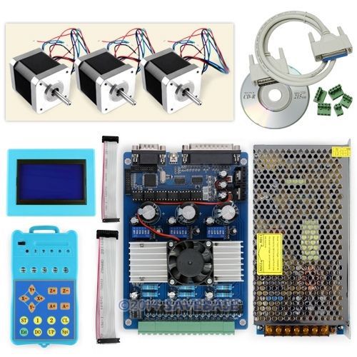
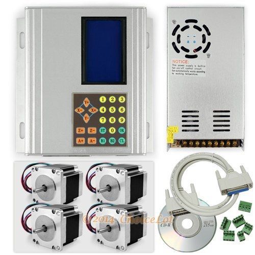
New CNC Standard 3Axis TB6560 Stepper Driver Full Kit & Motor/PSU/Keypad/Display
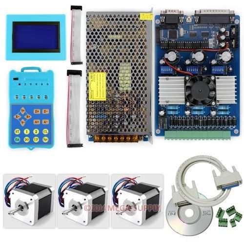
Advanced 3Axis CNC TB6560 Stepper Driver + Keypad + Display + Nema17 Motors +PSU
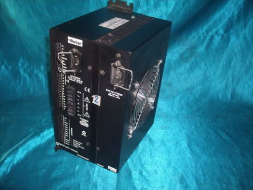
Parker Compumotor SX8 Series Microstep Drive 120V
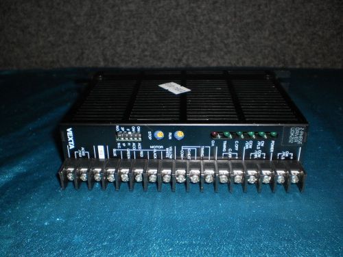
Vexta Oriental UDK2112 2 Phase Driver
People who viewed this item also vieved
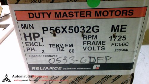
RELIANCE ELECTRIC P56X5032 FACE MOUNTED MOTOR 1 1800 230/460 TENV-EM F, NEW
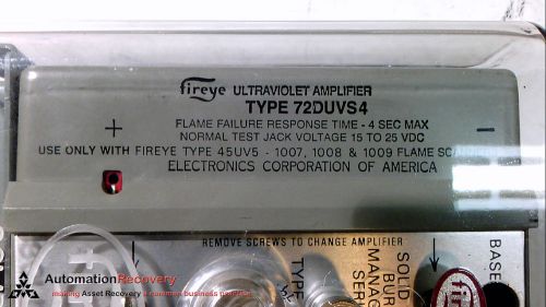
FIREYE 72D40 ULTRAVIOLET SELF-CHECK AMPLIFIER
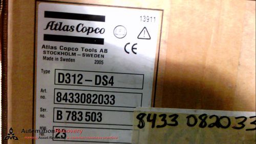
ATLAS COPCO 8433-082-33 DRIVE UNIT FOR ELECTRICAL TOOLS 300WATT 100-2, NEW
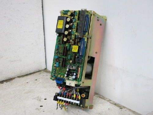
FANUC A06B-6047-H003 VELOCITY CONTROL UNIT.
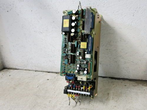
FANUC A06B-6047-H040 VELOCITY CONTROL UNIT
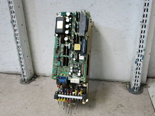
FANUC A06B-6047-H003 VELOCITY CONTROL UNIT
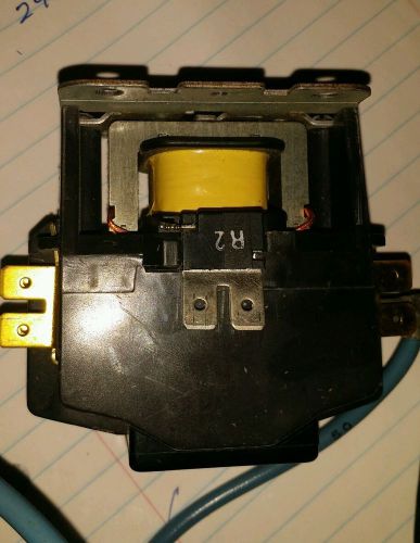
Used Furnas 45GG20AG 61357 Series C 2 Pole 24 Volt Coil Contactor
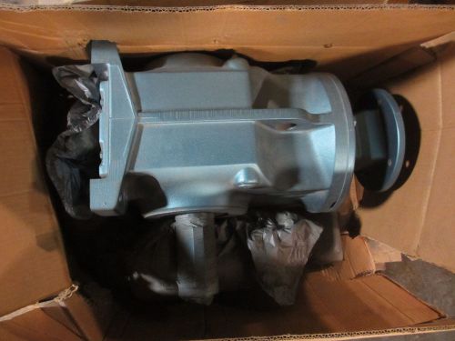
Sew EuroDrive Right Angle Gear Reducer K97AM184
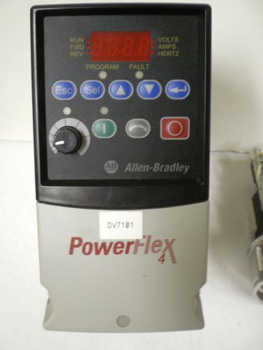
ALLEN BRADLEY VFD PowerFlex cat 22A-D1P4N104 SER A
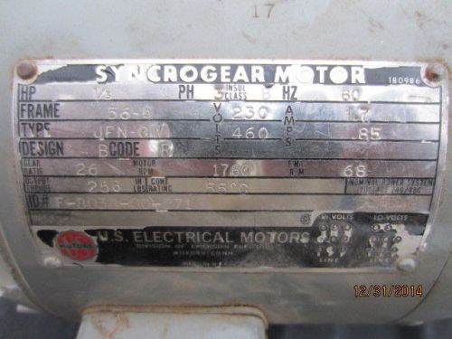
Syncogear Reducer Right Angle US Electrical Motor 1/3 HP, 68 RPM output
Vari-Speed Solid State Motor Speed Control ON/OFF New In Box
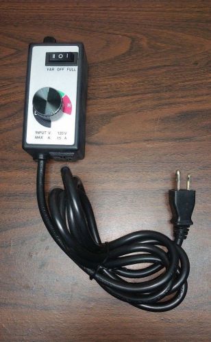
Router Variable Speed Controller Electric Motor AC Control Rheostat for Tools
KB DC MOTOR SPEED CONTROL KBDM-14PM NEW
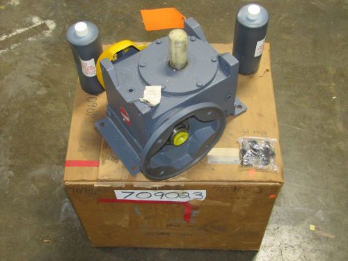
GRANT GEAR SVF350-10C-A SVF35010CA 10:1 RATIO SPEED REDUCER WORM GEAR BOX NIB

New Allen Bradley 154-A11NB /A Starting Torque Controller 11A 380-480VAC
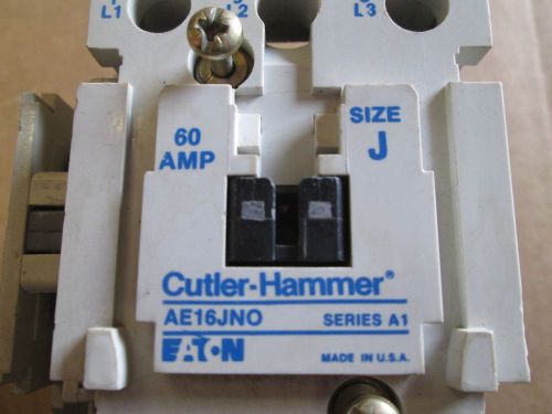
Eaton Cutler Hammer Contactor AE16JNO 600V 60 Amp 120V Coil Size J Ser A1
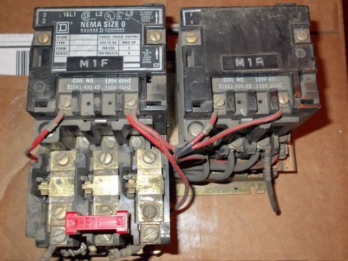
8736-SB04 Square D Nema Size 0 Starter Contactor 3 Phase Used
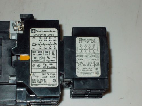
TELEMECHANIQUE CA2 D131 A 65 with LA1-D40 A 65 Contactor
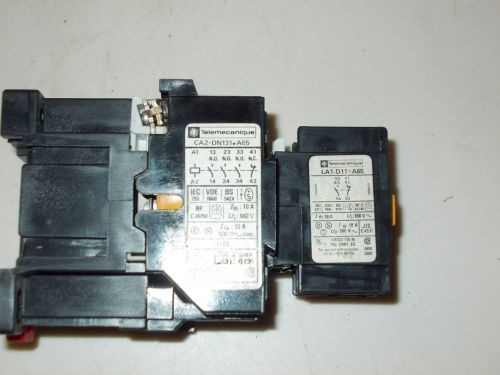
TELEMECHANIQUE CA2 D131 A 65 with LA1-D11 A 65 Contactor
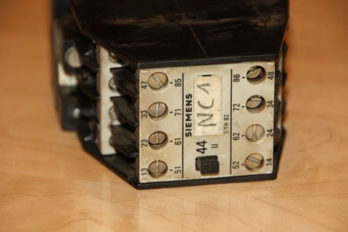
Siemens 3TH82 97-0A Working Pull
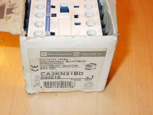
Telemecanique Square D Control Relay CA3KN31BD New In Original Box!
By clicking "Accept All Cookies", you agree to the storing of cookies on your device to enhance site navigation, analyze site usage, and assist in our marketing efforts.
Accept All Cookies