
US $730
| Condition: |
New: A brand-new, unused, unopened, undamaged item in its original packaging (where packaging is
applicable). Packaging should be the same as what is found in a retail store, unless the item is handmade or was packaged by the manufacturer in non-retail packaging, such as an unprinted box or plastic bag. See the seller's listing for full details.
...
|
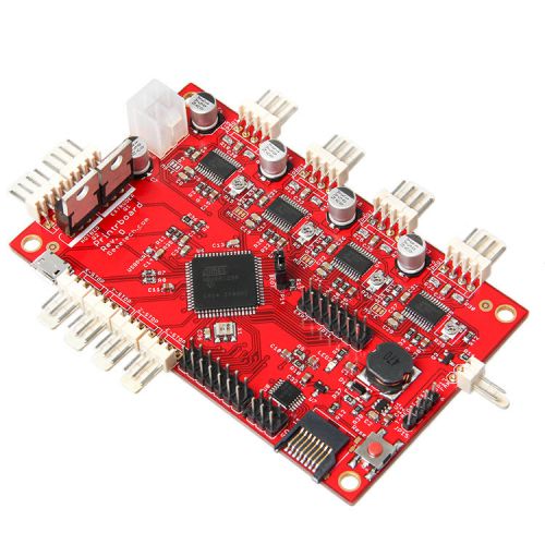
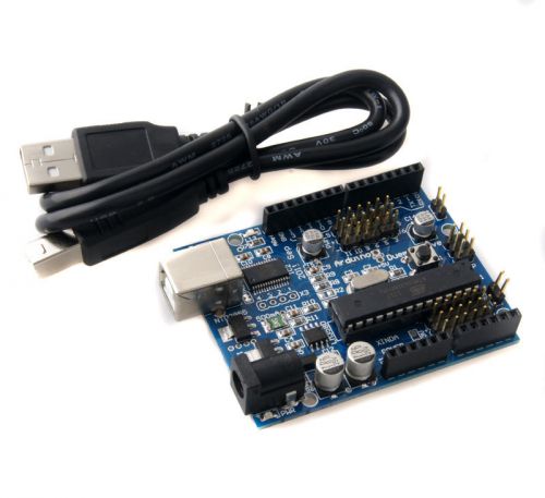
Brand | Geeetech |
Directions
Similar products from Electrical breadboards

5pcs Mini Solderless Prototype Breadboard 170 Tie-points for Arduino Shield
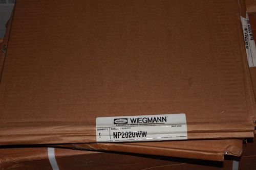
Wiegmann NP2020WW Enclosure Subpanel in White
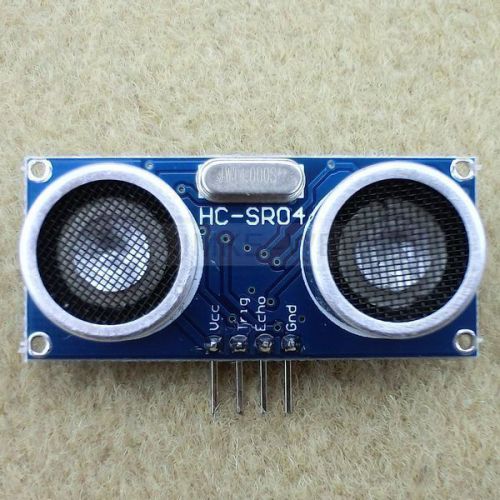
Arduino Ultrasonic Module HC-SR04 Distance Sensor

300mm 30cm Servo Extension Lead Wire Cable for Futaba JR Pack of 20pcs

New 300mm 30cm Servo Extension Lead Wire Cable for Futaba JR 50pcs

100pcs 200mm 1p to 1p female to female jumper wire Dupont cable for Arduino 20cm
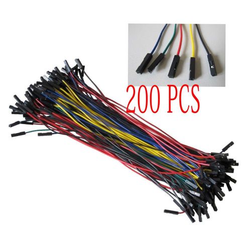
200pcs 200mm 1p to 1p female to female jumper wire Dupont cable for Arduino 20cm
100A Main Shut Off Safety Switch 100 Amp Service Panel Breaker Panel
NEW SIEMENS Main Lug 225A Circuit Breaker Panel 42 Space ES Series Load Center
AVRmega328P-PU Development Board for Arduino (Works with Official Arduino Board)
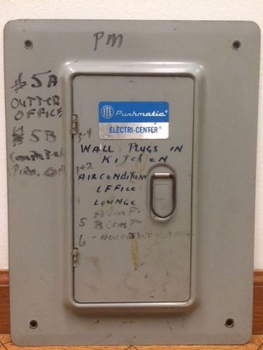
ITE SIEMENS PUSHMATIC BULLDOG GOULD 6 SPACE PANEL COVER 14.5" x 11"
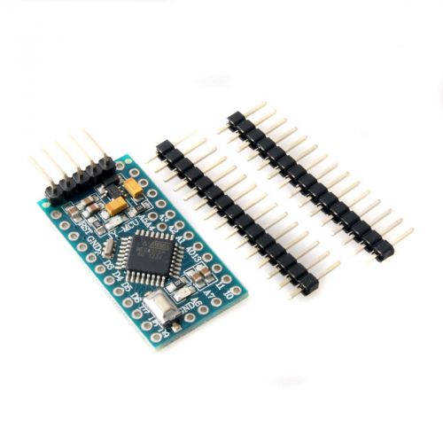
Pro Mini Microcontroller Circuit Board for Arduino (5V / 16MHz)
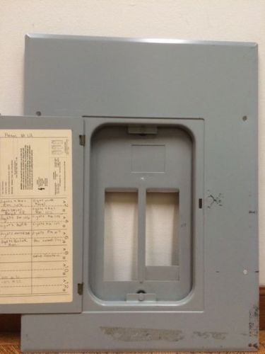
GE General Electric TLM12C Panel cover TLM1212C 100A 125A 120/240
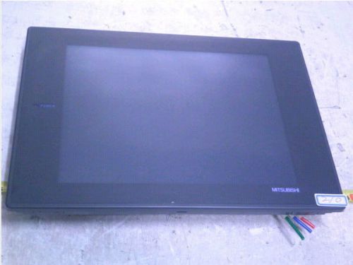
MITSUBISHI PANEL A970GOT-SBA A9GT-QBUSS
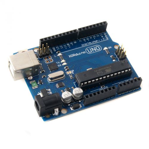
UNO R3 Development Board Microcontroller MEGA328P ATMEGA16U2 Compat for Arduino
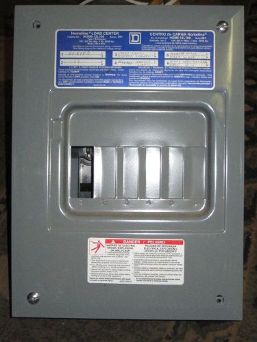
Homeline Square D Circuit Breaker Box
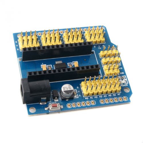
Multifunctional Nano UNO Expansion Board for Arduino Duemilanove 2009 / UNO R1
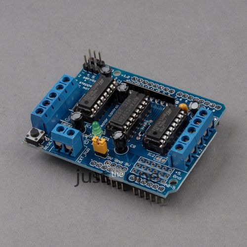
1Pcs Motor Control Shield Expansion Board L293D for Arduino Mega UNO Duemilanove
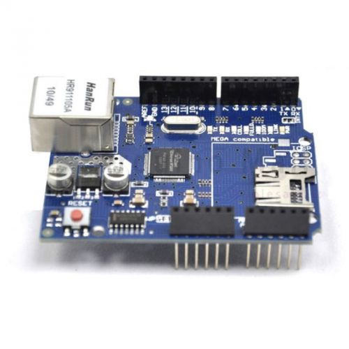
2012 version Ethernet Shield W5100 for Arduino UNO R3 Mega 2560 1280 A057
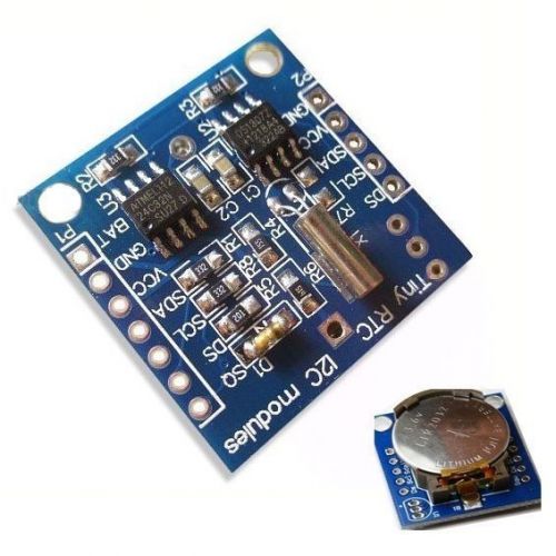
RTC I2C DS1307 AT24C32 Real Time Clock Module For Arduino AVR ARM PIC
People who viewed this item also vieved
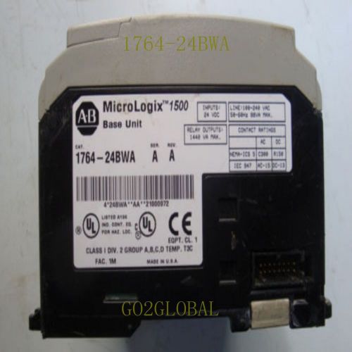
Allen-Bradley 1764-24BWA Allen Bradley PLC BASE Unit 60 days warrant
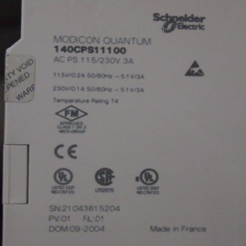
Power 140 Serial Schneider 140CPS11100 Supply Module 60 days warrant
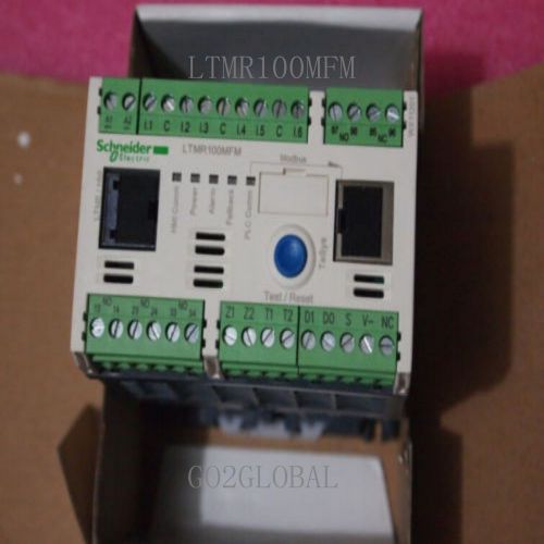
Schneider LTMR100MFM Module NEW Controller 60 days warrant
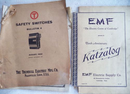
(2) Vintage Catalog Trumbull Electric 1922 and EMF Electric Supply 1937 N/R
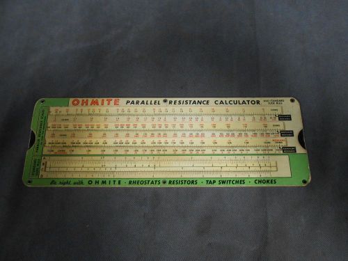
Vintage Cardboard Ohmite OHM's Law Parallel Resistance Calculator
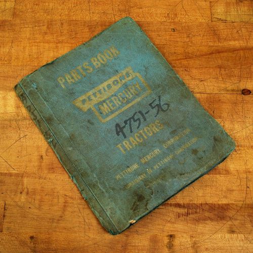
Pettibone A 751-56 Mercury Parts Catalog & Maintenance Manual
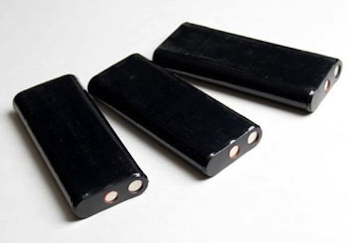
Digitrak Battery, New Nicd for Eclipse, Mark Series, LT Systems
ALTERNATING CURRENTS Electrical Manual Book by ICS STAFF 1935 edition #RB151
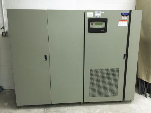
Liebert Npower MX 80kVA 64kW 3 Phase UPS Emerson Network Power & WJ1 Cabinet
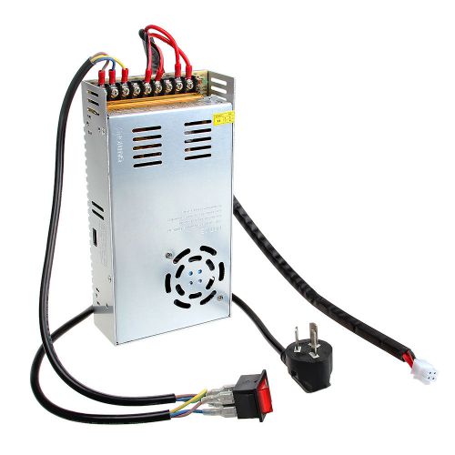
12V DC 29A adjustable 110V and 240V Power Supply for Reprap Prusa 3D Printer
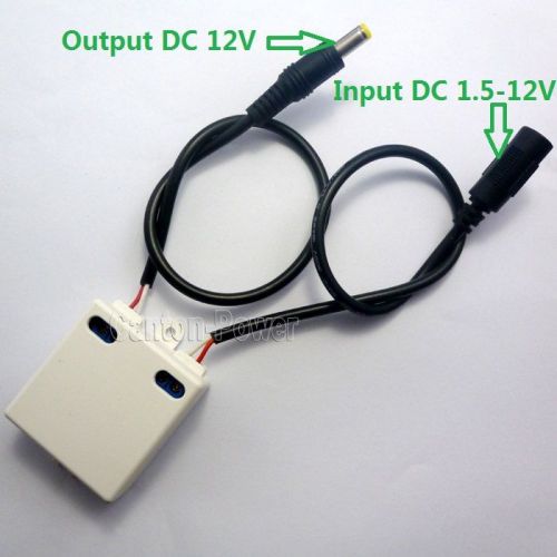
40W DC DC Converter 5V to 12V Boost Step-Up Power for IP PTZ Camera CCTV Router
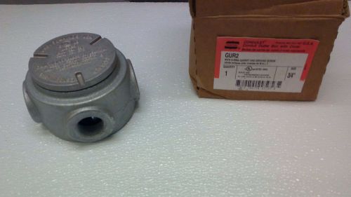
Crouse Hinds 3/4" GUR2 Explosion Proof Box 4 HUBS
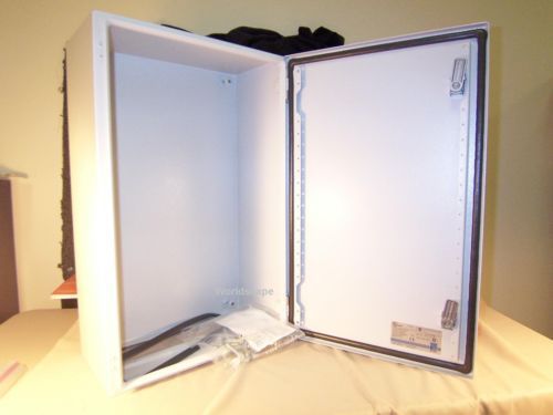
RITTAL AE1038.500 (1038500) NEMA 4 enclosure (NIB)
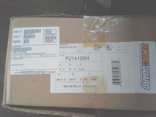
Hammond Box PJ14126H Enclosed Junction Box c/w 13R1311 Backplate! NEW IN BOX !
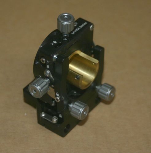
Newport LP-05A XY Lens Positioner 0.5 in. (12.7 mm) Diameter 2.0 in. Axis Height
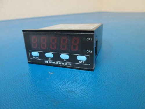
TOKYO FLOW METER CO Multi Digitalmeter EM-0100
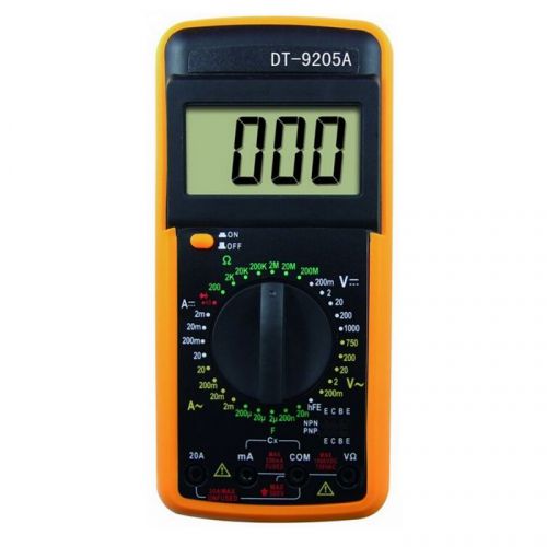
DT9205A Digital Multimeter Test AC/DC AMP VOLT Resistance Ammeter Voltmeter LCD
By clicking "Accept All Cookies", you agree to the storing of cookies on your device to enhance site navigation, analyze site usage, and assist in our marketing efforts.
Accept All Cookies