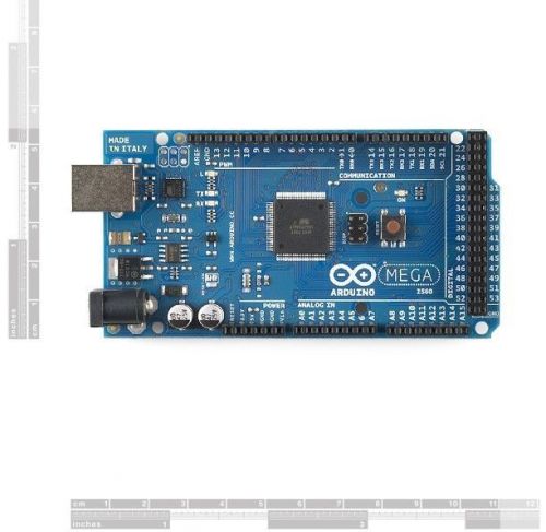
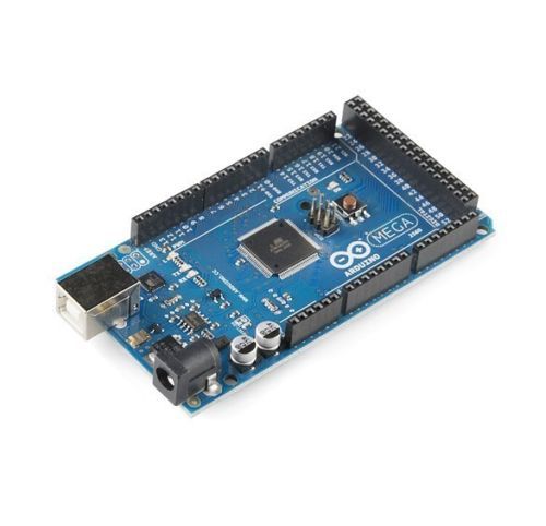
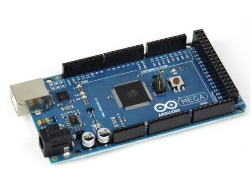
Welcome to visit our store. Have a nice buying experience. Description The Arduino Mega 2560 is a microcontroller board based on the ATmega2560 (datasheet). It has 54 digital input/output pins (of which 14 can be used as PWM outputs), 16 analog inputs, 4 UARTs (hardware serial ports), a 16 MHz crystal oscillator, a USB connection, a power jack, an ICSP header, and a reset button. It contains everything needed to support the microcontroller; simply connect it to a computer with a USB cable or power it with a AC-to-DC adapter or battery to get started. The Mega is compatible with most shields designed for the Arduino Duemilanove or Diecimila. The Mega 2560 is an update to the Arduino Mega, which it replaces. Summary Microcontroller ATmega2560 Operating Voltage 5V Input Voltage (recommended) 7-12V Input Voltage (limits) 6-20V Digital I/O Pins 54 (of which 14 provide PWM output) Analog Input Pins 16 DC Current per I/O Pin 40 mA DC Current for 3.3V Pin 50 mA Flash Memory 256 KB of which 8 KB used by bootloader SRAM 8 KB EEPROM 4 KB Clock Speed 16 MHz Power The Arduino Mega can be powered via the USB connection or with an external power supply. The power source is selected automatically. External (non-USB) power can come either from an AC-to-DC adapter (wall-wart) or battery. The adapter can be connected by plugging a 2.1mm center-positive plug into the board's power jack. Leads from a battery can be inserted in the Gnd and Vin pin headers of the POWER connector. The board can operate on an external supply of 6 to 20 volts. If supplied with less than 7V, however, the 5V pin may supply less than five volts and the board may be unstable. If using more than 12V, the voltage regulator may overheat and damage the board. The recommended range is 7 to 12 volts. The Mega2560 differs from all preceding boards in that it does not use the FTDI USB-to-serial driver chip. Instead, it features the ATmega16U2 (ATmega8U2 in the revision 1 and revision 2 boards) programmed as a USB-to-serial converter. Revision 2 of the Mega2560 board has a resistor pulling the 8U2 HWB line to ground, making it easier to put into DFU mode. Revision 3 of the board has the following new features: 1.0 pinout: added SDA and SCL pins that are near to the AREF pin and two other new pins placed near to the RESET pin, the IOREF that allow the shields to adapt to the voltage provided from the board. In future, shields will be compatible both with the board that use the AVR, which operate with 5V and with the Arduino Due that operate with 3.3V. The second one is a not connected pin, that is reserved for future purposes. Stronger RESET circuit. Atmega 16U2 replace the 8U2. The power pins are as follows: VIN. The input voltage to the Arduino board when it's using an external power source (as opposed to 5 volts from the USB connection or other regulated power source). You can supply voltage through this pin, or, if supplying voltage via the power jack, access it through this pin. 5V. The regulated power supply used to power the microcontroller and other components on the board. This can come either from VIN via an on-board regulator, or be supplied by USB or another regulated 5V supply. 3V3. A 3.3 volt supply generated by the on-board regulator. Maximum current draw is 50 mA. GND. Ground pins. Memory The ATmega2560 has 256 KB of flash memory for storing code (of which 8 KB is used for the bootloader), 8 KB of SRAM and 4 KB of EEPROM (which can be read and written with the EEPROM library). Input and Output Each of the 54 digital pins on the Mega can be used as an input or output, using pinMode(), digitalWrite(), and digitalRead() functions. They operate at 5 volts. Each pin can provide or receive a maximum of 40 mA and has an internal pull-up resistor (disconnected by default) of 20-50 kOhms. In addition, some pins have specialized functions: Serial: 0 (RX) and 1 (TX); Serial 1: 19 (RX) and 18 (TX); Serial 2: 17 (RX) and 16 (TX); Serial 3: 15 (RX) and 14 (TX). Used to receive (RX) and transmit (TX) TTL serial data. Pins 0 and 1 are also connected to the corresponding pins of the ATmega16U2 USB-to-TTL Serial chip. External Interrupts: 2 (interrupt 0), 3 (interrupt 1), 18 (interrupt 5), 19 (interrupt 4), 20 (interrupt 3), and 21 (interrupt 2). These pins can be configured to trigger an interrupt on a low value, a rising or falling edge, or a change in value. See the attachInterrupt() function for details. PWM: 0 to 13. Provide 8-bit PWM output with the analogWrite() function. SPI: 50 (MISO), 51 (MOSI), 52 (SCK), 53 (SS). These pins support SPI communication using the SPI library. The SPI pins are also broken out on the ICSP header, which is physically compatible with the Uno, Duemilanove and Diecimila. LED: 13. There is a built-in LED connected to digital pin 13. When the pin is HIGH value, the LED is on, when the pin is LOW, it's off. TWI: 20 (SDA) and 21 (SCL). Support TWI communication using the Wire library. Note that these pins are not in the same location as the TWI pins on the Duemilanove or Diecimila. The Mega2560 has 16 analog inputs, each of which provide 10 bits of resolution (i.e. 1024 different values). By default they measure from ground to 5 volts, though is it possible to change the upper end of their range using the AREF pin and analogReference() function. There are a couple of other pins on the board: AREF. Reference voltage for the analog inputs. Used with analogReference(). Reset. Bring this line LOW to reset the microcontroller. Typically used to add a reset button to shields which block Package list 1 X original Arduino Mega2560 Payment 1.We accept PayPal only. 2.Payment must be received within 7 business days of auction closing.,or a unpaid case will be opened. Delivery details 1.Standard shipping carrier is ePacket with tracking code for United States address,delivery within 7-14 busienss days. 2.For outside US address,standard shipping carrier is Hong Kong Post without tracking code,delivery within 25-30 business days. We provide a free tracking for order above 45USD. Please contact us if you want to add a tracking code for small orders. 3.Express shipping like DHL,Fedex,UPS,TNT is also avaiable if you are willing to pay extra. DHL is our standard shipping carrier for Expedited shipping,please contact us if you want a different carrier. Terms of sales 1.Customs duties or taxes are buyer's resposibility for all of the listings.Please check with your local customs office if you have any doubts. 2.Please confirm you are putting a correct and complete shipping address here.You are resposible for extra charge if your package been returned because of wrong address.If packages return because of wrong address,you will have to bear extra cost of shipping. Contact us 1.We are always here for you,offering friendly, comprehensive customer service every step of the way. Please follow the good eBay practice to contact us if any doubts and problems.We sincerely hope our item and customer service can give you the BEST BUYING EXPERIENCE on eBay. 2.We greatly appreciate your POSITIVE feedback. Please do NOT leave negative or neutral feedback without any contact. Engineered for professional eBay sellers! On Dec-15-14 at 22:54:26 PST, seller added the following information:
By clicking "Accept All Cookies", you agree to the storing of cookies on your device to enhance site navigation, analyze site usage, and assist in our marketing efforts.