US $6.99
| Condition: |
New: A brand-new, unused, unopened, undamaged item in its original packaging (where packaging is
applicable). Packaging should be the same as what is found in a retail store, unless the item is handmade or was packaged by the manufacturer in non-retail packaging, such as an unprinted box or plastic bag. See the seller's listing for full details.
...
|
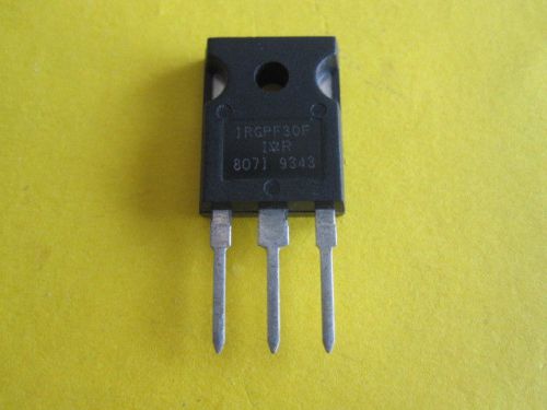
Brand | International Rectifier Corp. |
| MPN | united states | ||
| Model | IGBTs irgpf30f | ||
| Country/Region of Manufacture | United States |
Directions
Similar products from General & Complementary Transistors
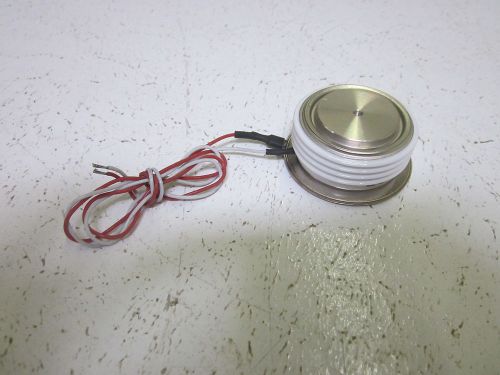
POWEREX 104X125DA151 THYRISTOR *NEW OUT OF A BOX*
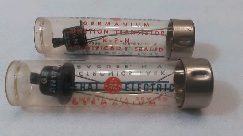
2 GENERAL ELECTRIC GERMANIUM TRANSISTORS 2N-170 HAT STYLE NOS
95 International Recifier IRF330 400V, 5.5A, 1.0 ohm, 75W TO-3 N-Channel MOSFET
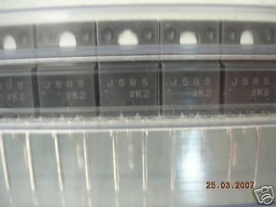
J585 ( Si NPN Lo-Pwr BJT) 2sj585 j585
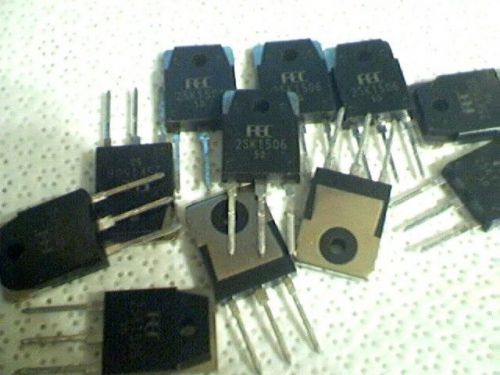
12 FEC 2SK1506 POWER Mosfet Transistors

10pcs BFG591 ORIGINAL NXP 7 GHz Wideband Transistor
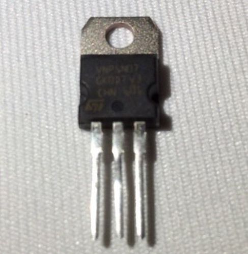
VNP5N07 POWER TRANSISTOR NEW X10
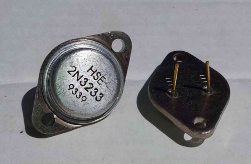
LOT OF 5 PIECES (MORE CHEAPER) NOS 2N3233 Power Transistor TO-3 !FREE USA SHIP!
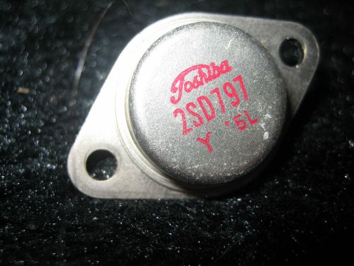
TOSHIBA TRANSISTOR 2SD797 Y 5L NEW
Lot of 15 pcs NOS MPSA29 NPN Darlington Transistor !!!USA SHIPPER!!!
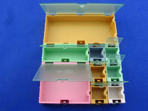
1set SMT SMD Electronic Component Box,Plastic Storage box,total 9pcs for 4 sizes
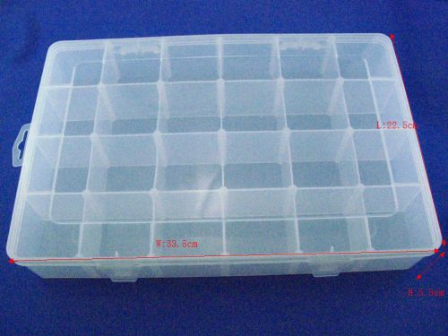
2pcs/lot,Electronic Components Storage Box, 24 lattice/blocks, moveable clapboar
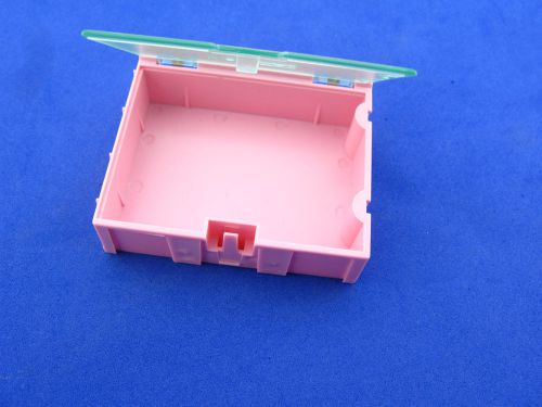
6pcs SMT SMD Electronic Component Box,Plastic Storage Box, 75 x 63 x 21.5MM
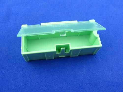
20pcs SMT SMD Electronic Component Box,Plastic Storage Box,75 x 31.5 x 21.5 MM
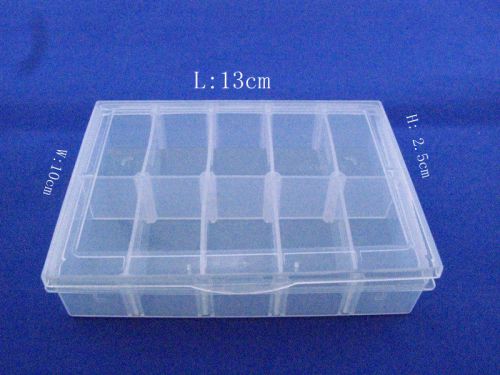
5pcs/lot, Electronic Components Storage Box, 10 lattice, moveable clapboard ,New
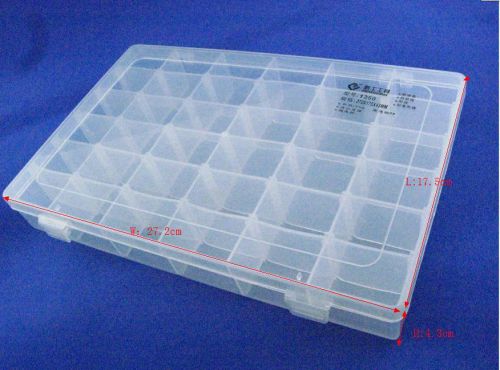
2pcs/lot,Electronic Components Storage Box, 36 latticeblocks, moveable clapboard
People who viewed this item also vieved
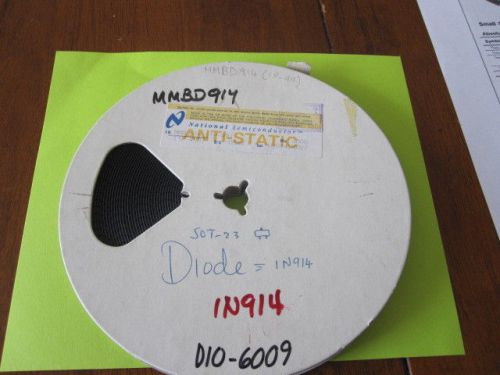
MMBD914 SMALL SIGNAL DIODE(25 ITEMS)

NTE 246, 384, 519,116, 283, 133 5166A
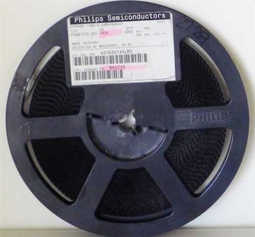
BAV23S PHILIPS DUAL HIGH VOLTAGE SWITCHING DIODES REEL OF 3729 - BRAND NEW
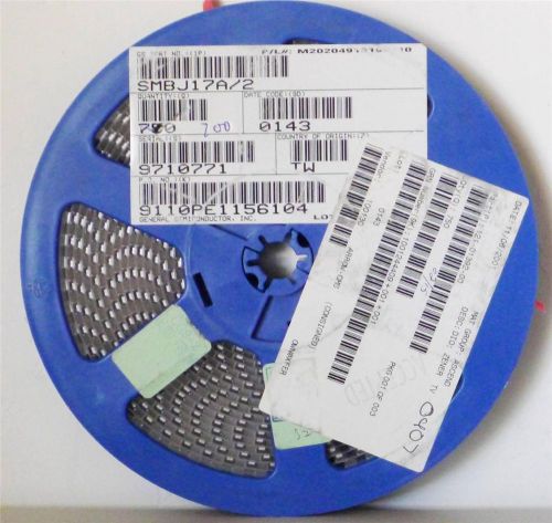
SMBJ17A/2 GENERAL SEMI TVS DIODE-REEL OF 700 - BRAND NEW
LTA150XH-L06 15" LCD display panel PC.
White 0.96 inch I2C TWI Serial 128 X 64 OLED Display Module for Arduino
Ocular 240X160 Monochrome Graphic LCD Display Module 3"x4" Arduino Raspberry Pi
LCD TFT TOSHIBA TFD60W11-MM 234(V)x320(H) 6"
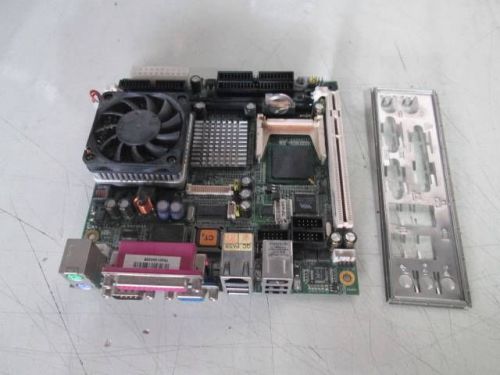
IPOX IP-4MTS7B Industrial Computer Motherboard mPGA 478 Socket
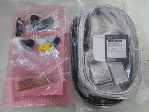
kit Edwards D37207592 D37207593 Cable Assy XLR 4W/6W 5M
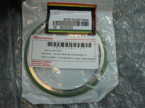
Edwards B27158171 ISO-100 Trapped O-Ring Seal Viton
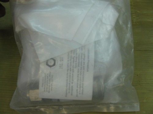
Applied Materials 3300-00271 FTG CPLG QDISC BLKHD 1/2BODY X 1/2T SST A-LOK
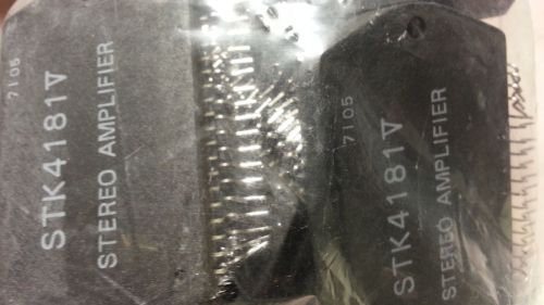

LM 12 LM12 LM12CLK 80W Operational Amplifier Power Amplifier TO-3 new tested

5x 10 Surface Mount Devices Bridge Rectifiers MB6S High Surge Current Capability
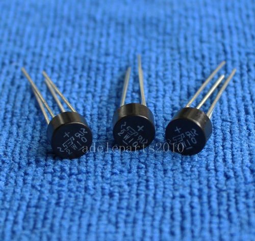
10pcs 2W10 2A 1000V Bridge Rectifier SEP

NEW GENERAL ELECTRIC GE C45D DIODE RECTIFIER D488492
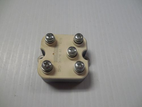
SEMIKRON POWER BRIDGE RECTIFIER SKD 30/16 A1 SKD3016A1 6715
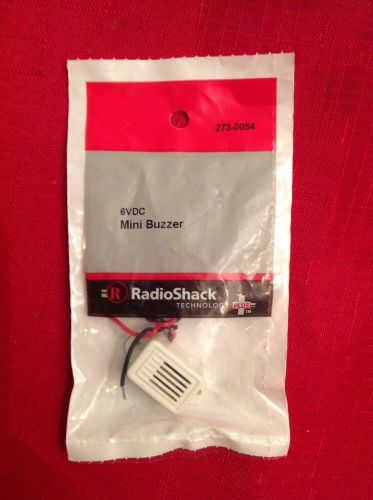
6VDC Mini Buzzer #273-0054 By RadioShack
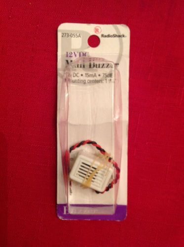
12VDC Mini Buzzer #273-055A By RadioShack
![[1x] Small 1W Speakers - 8 ohm 30 x 20 x 4mm for DIY Arduino, Phone Repair](/_content/items/images/35/3892635/001.jpg)
[1x] Small 1W Speakers - 8 ohm 30 x 20 x 4mm for DIY Arduino, Phone Repair
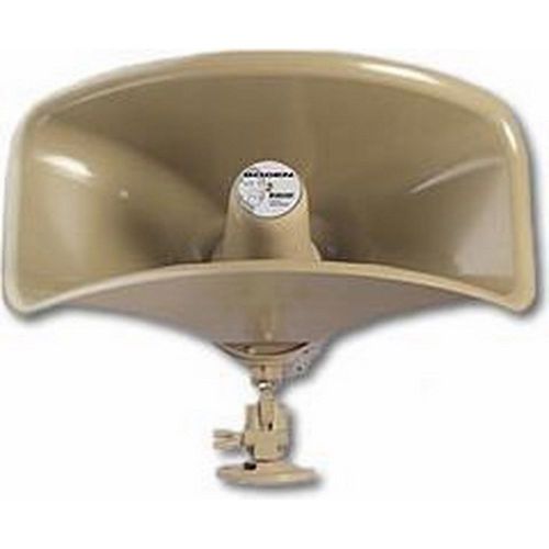
BRAND NEW - Bogen Wide Dispersion Reentrant Horn Loudspkr
By clicking "Accept All Cookies", you agree to the storing of cookies on your device to enhance site navigation, analyze site usage, and assist in our marketing efforts.
Accept All Cookies