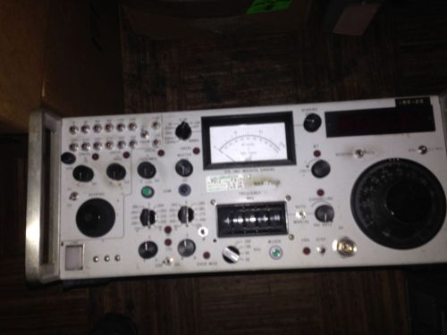
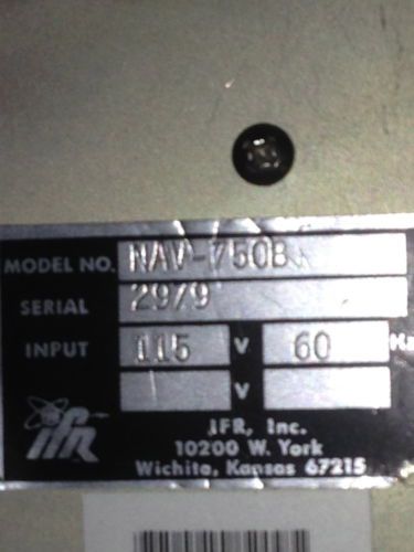
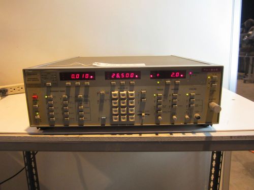
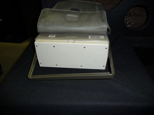
IFR NAV-750B VOR/LOC/COMM/G/S and MKR BEACON Bench Test Set Specifications are from IFR and may vary slightly due to upgrades, options, or revisions this unit may or may not have. The unit is guaranteed to work for 30-days. The Unit's Serial Tag Reads: Model Number: NAV-750B Serial Number: 2979 Input Power: 115V, 60 Hz General Description: The NAV-750 series Precision Simulators are completely self-contained units designed for the semi-automatic functional testing and calibration of airborne VOR, LOC, G/S, MKR and COMM receivers. Complete VOR, LOC, COMM, MKR and G/S generator ARINC two-out-of-five wire frequency selection output 25 kHz spacing with automatic channeling 40 paired LOC-G/S frequencies Continuously variable attenuator -6 dBm (112,000 µV) to -120 dBm (.224 µV) Automatic selection of VOR or LOC modulation Built-in bearing monitor Generator Description: Semi-automatic generator features make it convenient for test operation. The RF generator is selectable in 25 kHz steps from 108 to 157.950 MHz and from 329 to 335 MHz. No operator tuning or leveling is required. The frequency thumbswitch controls the frequency when the MAN/AUTO switch is selected to MANUAL. When the channeling rate control is in the maximum counter-clockwise position and MAN/AUTO switch is switched to AUTO, the frequency selected on the thumbswitch will hold. Clockwise rotation of channeling rate control from stop beings to advanced frequency upward in 25, 50, 100 or 200 kHz steps as selected by kHz Step switch. At 117.95 MHz, 135.975 MHz and 335.976 MHz channeling automatically stops and the END indicator comes on. The two out of five remote channeling also follows the automatic channeling stepping. When stepping (or manually selecting) a localizer channel, the modulation will internally switch to localizer unless the LOC-G/S switch is in the G/S position. If it is in the G/S position, G/S modulation will be internally selected and the RF generator will internally switch to the assigned G/S channel in the 330 MHz band. G/S operation may be select4ed by setting the actual G/S frequency on the thumbwheel FREQUENCY switch. The output frequency may be deviated by up to ±50 kHz on the 108 to 157.950 MHz band and ±150 kHz in the 330 MHz band by the change in F control. The generator frequency is monitored by the counter when selected by the BEARING/FREQ switch (1 kHz resolution or 0.1 kHz resolution). A proportional temperature controlled crystal reference controls both the generator and counter. External modulation may be added to any signal through rear panel jack. A demodulation output is provided on the rear panel. MKR Description: Marker Beacon generator covers frequencies from 70 MHz to 79.9 MHz in 25 kHz steps. 1020 Hz, 400 Hz, 1300 Hz, and 3000 Hz tone modulation is available at 95%, calibrated, or 0 to 96%, variable, modulation level between 74 and 79.9 MHz. VOR Description: The VOR bearing selection is accomplished by push buttons on the twelve 30° bearings. The six digit counter displays the bearing to 0.01° resolution, counting from the digital bearing source. Two push buttons, +10° and -10°, add or subtract 10° from any bearing selected. The bearing knob rotates a 40 tooth gear which has a photo interrupter to pulse upward or downward the bearing selected. This system gives the ability to make analog bearing adjustments to center a left-right needle. The pulses are selectable in 0.01° steps or 0.05° steps. The 30 Hz VOR tones are both derived from a 2.16 MHz crystal. The 9960 Hz tone frequency is phase-locked to the 2.16 MHz crystal. A 1020 Hz tone (0-60%) is available. Each VOR tone appears on a rear panel jack. An additional jack supplies composite signals. LOC Description: Localizer deviation can be selected ±0.046 DDM, ±0.093 DDM, ±0.155 DDM, ±0.200 DDM, and continuously adjustable ±0.400 DDM. One tone may be deleted while the other remains at 20%. The Master Modulation control allows further adjustment of modulation. COMM Description: COMM frequencies from 118 to 157.950 MHz are selectable in 25 kHz steps. A 1020 Hz tone can modulate 0-60% for audio tests. External modulation also may be added through the external modulation jack. G/S Description: G/S deviation can be selected ±0.045 DDM, ±0.091 DDM, ±0.175 DDM, ±0.400 DDM, and continuously adjustable ±0.800 DDM. One tone may be deleted while the other remains at 40%. The Master Modulation control allows further adjustment of modulation. The phase of the 90 and 150 Hz tones is fixed to within ±0.1° unless the ? button is pressed. The phase of the 90 and 150 Hz tones is then retarded at five times the angle selected by the VOR bearing selector. RF Power Out Specifications: Accuracy: ± 1.5 dB from -6 dBm to -50 dBm, ± 2.5 dBm from -50 dBm to -120 dBm Leakage: Less than 3 µV at 334.700 MHz, 1 µV at 108.000 MHz induced in a two-turn, one inch diameter (#20 gauge wire) loop, measured one inch away from any surface and into a 50 ohm receiver. Internal Temperature Controlled Crystal Oscillator (TCXO) Specifications: Accuracy: Better than ± 1 ppm for 15° to 35°C After Calibration at 25°C: Better than ± 3 ppm for 10° to 45°C Aging: Less than ± 2 ppm/year Clock Oscillator (2.16 MHz) Specifications: Accuracy: ± 0.02% Modulation Specifications: AM Depth: VOR: 0% to 98% LOC: 0% to 98% COMM: 0% to 98% G/S: 0% to 98% MKR: 0% to 98% Accuracy: As listed below, with front panel Modulation Controls in CAL positions. Note: 0-100 meter scale is selected for G/S and MKR tones. All other tones are measured on 0-30% Modulation Scale. All values are for single-tone modulation of the indicated frequency. MKR tones maximum modulation depth capability is at least 60% from 70.000 to 74.000 MHz. All values are measured at the RF Output Connector. Modulation Frequency RF Range Acceptable Level of Modulation (absolute) at RF output Connector 30 Hz VOR 30% (± 1.2%) 9960 Hz VOR 30% (± 1.2%) 90 Hz LOC 20% (± 0.8%) 150 Hz LOC 20% (± 0.8) 90 Hz G/S 40% (± 1.6%) 150 Hz G/S 40% (± 1.6%) 1020 Hz COMM 30% (± 1.2%) 400 Hz MKR 95% (± 2.85%) 1300 Hz MKR 95% (± 2.85%) 3000 Hz MKR 95% (± 2.85%) Tones Specifications: Distortion: 9960 Hz: 1.5% Max 30 Hz Ref: 0.5% Max 30 Hz Var: 0.5% Max 1020 Hz Ref: 0.5% Max 90 Hz: 0.4% Max 150 Hz Var: 0.4% Max 400 Hz Var: 0.7% Max 1300 Hz: 0.7% Max 3000 Hz Var: 0.7% Max Frequencies: 90 Hz: ± 0.2% 150 Hz: ± 0.2% 30 Hz Ref: ± 0.2% 30 Hz Var: ± 0.2% 9960 Hz: Phase-locked to 30 Hz REF tone 1020 Hz: ± 0.5% 400 Hz: ± 0.7% 1300 Hz: ± 0.7% 3000 Hz: ± 0.7% Note: The 90 Hz, 150 Hz, 30 Hz REF and 30 Hz VAR tones are derived from the 2.16 MHz crystal oscillator and the tones reflect the accuracy of the oscillator. Tone distortion should increase no more than 0.2% at the RF DEMOD Connector. DDM Accuracy Specifications: DDM Setting Composite Audio Error (DDM) Composite Modulation Error (DDM) Localizer: .046 .00101 .00283 .093 .00102 .00370 .155 .00103 .00720 .200 .00104 .00900 Glide Slope: .045 .00101 .00280 .091 .00102 .00464 .175 .00104 .00800 .400 .00104 .01700 Note: Composite Audio Error is .001 DDM + .02% DDM setting. Composite Modulation Error is .001 DDM + 4% DDM setting. VOR Section Specifications: Bearing Selection: Twelve preset bearings each 30°. Additional +10° and -10° steps from any bearing selected. Variable Bearing Control provides continuous bearing adjustment in 0.01° or 0.05° steps. Bearing Accuracy: ± 0.05° on all bearings. Bearing Monitor: By independent counter. Displays bearing to 0.01° resolution. VOR Tones: 30 Hz REF and 30 Hz VAR tones are derived from 2.16 MHz crystal oscillator. 9960 Hz tone is frequency locked to the 2.16 MHz crystal oscillator. IDENT Tone: 1020 Hz tone may be added from 0 to 60% modulation. LOC Section Specifications: Deviation: ± 0.046 DDM, ± 0.93 DDM, ± 0.155 DDM, ± 0.200 DDM and continuously adjustable ± 0.4 DDM. One tone may be deleted while the other is at 20% Centering Accuracy: ± 0.001 DDM (± .85 µA) Tones: 90 Hz and 150 Hz tones are phase-locked to ± 0.1° or phase variable at five times the angle selected by the VOR bearing selector. 1020 Hz tone may be added. G/S Section Specifications: Deviation: ± 0.045 DDM, ± 0.091 DDM, ± 0.175 DDM, ± 0.400 DDM and continuously adjustable ± 0.8 DDM. One tone may be deleted while the other is at 40% Centering Accuracy: ± 0.001 DDM (± 1 µA) Tones: 90 Hz and 150 Hz tones are phase-locked to ± 0.1° or phase variable at five times the angle selected by the VOR bearing selector. 1020 Hz tone may be added. COMM Section Specifications: Modulation: 1020 Hz, 400 Hz, 1300 Hz and 3000 Hz tones 0-60% for audio tests. External modulation may be added. MKR BEACON Section Specifications: Tones: 1020 Hz, 400 Hz, 1300 Hz, and 3000 Hz. Modulation: Selectable at 95% (± 3%) modulation in CAL. Variable 0-98% in UNCAL. RF Generator Specifications: Frequency Range: 70.000 to 79.900 MHz, 108.000 to 156.000 MHz and 329.000 to 335.000 MHz in 25 kHz increments. Frequency Selection: Manually by thumbwheel switch. Automatically up only at a variable rate in 25, 50, 100, or 200 kHz increments. Auto channeling stops at 117.950 and 135.975 MHz. External channeling may be added. Variable Frequency: ± 50 kHz minimum at 108.000 to 156.000 MHz and ± 150 kHz minimum from 329.000 to 335.000 MHz. Generator remains phase-locked at all fixed and variable frequencies. Frequency Accuracy: Controlled by oven crystal to ± 0.0001%. Frequency Monitor: By independent counter to 1 kHz or 0.1 kHz resolution. Counter time base ± 0.0001% Remote Function: Frequency in use fed to rear panel as 2 out of 5 channeling and parallel BCD. Remote channeling follows manual or auto selection. Modulation Selection: Automatic by frequency selected. VOR modulation applied if on any VOR frequency, LOC modulation applied if on any LOC frequency, G/S modulation applied if on any G/S frequency. Tone frequency selectable for MKR operation. External Modulation Specifications: Note: External modulation may be added to any signal through External Modulation Input Connector (J18). When not in use, External Modulation Connector must be terminated with 100 Ohms or less. Impedance (J18): 1 kOhm nominal Sensitivity: 9.1 V p-p (± 0.6V) = 90% (Master Modulation Level Control set to CAL) DEMOD Output Specifications: Impedance (J23): For any signal at a rear panel jack (J23). Minimum resistance is 1 kOhm. DC Voltage: 3.75V (± 0.3V) AC Voltage: 2.72V (± 0.2V) = 100% Modulation General Characteristics: Power Requirements: 105 to 120 VAC or 220 to 250 VAC, 50 to 400 Hz (Cooling fan 50/60 Hz only. Need a different fan for 400 Hz operation.) Power Consumption: 250 W maximum, 110 W nominal Ships to US locations only.
By clicking "Accept All Cookies", you agree to the storing of cookies on your device to enhance site navigation, analyze site usage, and assist in our marketing efforts.